Bob's Lost In Space B9 Robot Project | home
Misc. Parts | Motor Shaft Extensions | Knees & Hinges | Treadsections | Tread Making | TreadMaking from Tires | Drive Parts | Drive & Tread Installation | Tread movie | Barry's Tread Movies | Drive Upgrade | Legs | Donut & Waist plate | First Stackup | Torso | Neon | Arms | Microphone & Knob | Chest Buttons | Power Pack | Torso Vents Misc | Making Vents | Large Vent Drawings | Arm Mechanism #1 | B9 Arm Mech Dev. | Wrists & Claws | Collar | Radar | Motorizing Ears | Making Sensors | Brain | Brain Cup & Light Rods | Bulbs & Wiring Diagrams | My Old Robots | B9 Builder's & Info Sites | Related Links | Building Reference Info | Parts Drawing Links | Site Revisions | Final Leg Assembly | Leg & Hip Assembly | Leg-Hip Action | Non-B9 Projects | 2008 TX BUILD-OFF | 2008 TX BUILD-OFF PAGE 2 | RoboCon 2009
Final Leg Assembly
I am calling this Final Assembly because this is where I will be bringing it all together from the ground up, so to speak.
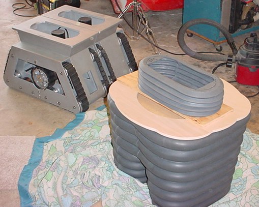
I set out to build the base section of the internal supports which will go just above the knees and "crotch" of the upper rubber knee section. I chose this initial height level for the mid level support section. It will hold the upper support section that also will allow overall remote height control and also forward and back "waist" tilting. My parts are coming for this function and I will include info on how all that works (well I am assuming it is going to work!).
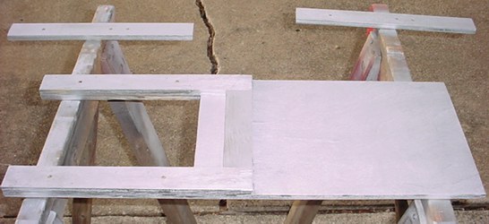
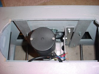
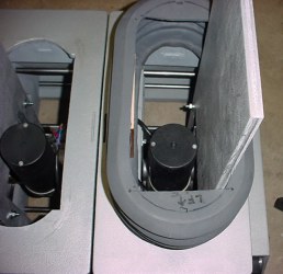
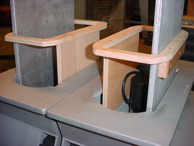
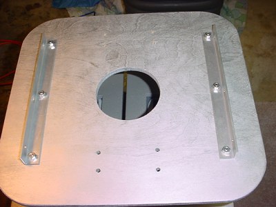
This requires an internal support system from the treadsections up since now the knees and legs have no support and are completely flexible. This is a top view down of test fitting of the support for one side.
A picture of the clearance I provided for the knees to fit down into the treadsection top plate around the supports.
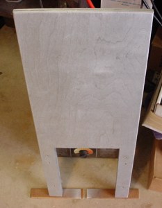
One of the supports painted.
Support with mounted spacers and additional spacers for inside the treadsection.
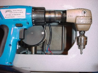
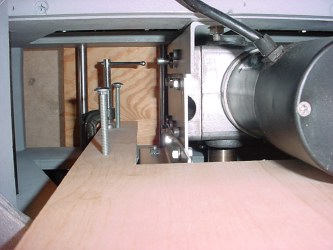
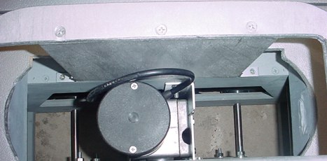
Just thought you'd like to see how to drill holes inside the treadsection after it is all together. For mounting the support system, I had to set this up and even make a special "stubby" bit by trimming down the back end and drill end of a standard drill and re-sharpening it. Otherwise you can't get a regular size drill bit inside.
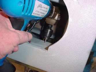
This is how it fits in from the top, of course I was holding the camera with my other hand that I would use to actually drill the hole by holding the right angle drive to properly guide the bit. I have about 1/2" to spare with this setup as you can see at the back of the right angle drive.
This is an old right angle drive (from the '60's) I refurbished to use as the newer one I have has a larger case and is too large to fit into the center area of the treadsection.
Here are the two inner spacers installed, using carriage bolts from the "tread belt" side.
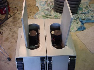
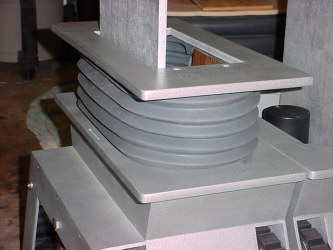
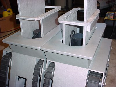
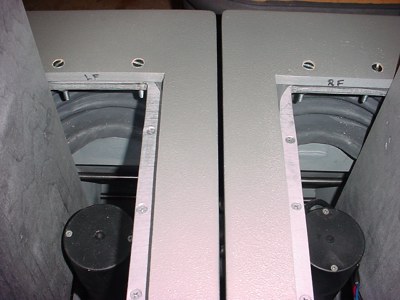
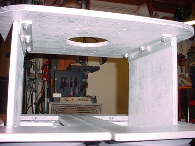
Here are both supports in place.
These will provide the height for the secondary support level approx 7.5" above the kneeplates (just above the max height of the 'crotch' section of the rubber legs.
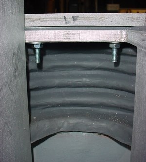
Here is a view of the support bolts.
One of the knees.
I used a sharpie and marked to cut out the top of the knees. The silicone at the top section of the knees is approx 1/4" thick but can be cut with scissors. Details on the template, etc for this are on my Knees page.
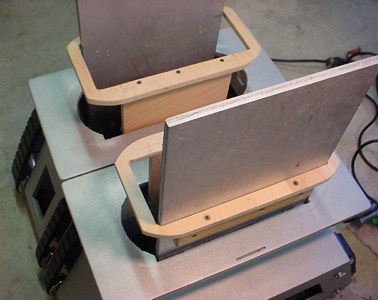
Test fit of knee plate.
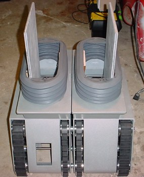
Both knees test fit.
Another view.
I had to create a way to support the flexible rubber knees and to keep my kneeplates stationary and fixed in place. I do not want the knee plates moving around due to the flexible knees and hitting each other. With some measuring and tracing I came up with this. It will also provide support for the batteries.
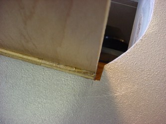
Made from 1/2" birch plywood for lightweight and strength this seems to be the simplest way to accomplish it. Unfortunately you can see that this is limiting space for the batteries. My larger batteries will sit on top of the kneeplates inside the lower portion of the legs.
If you wonder why there is a gap between the vertical support and the top plate of the treadsection, that is because the rubber knees have a bottom flange of rubber that slips into the opening so the supports are spaced away from the opening. You can see that on my knees page.
Here are the pieces painted and assembled.
The inner support piece is simply bracketed in place on the left and right side in the treadsection with small right angle brackets.
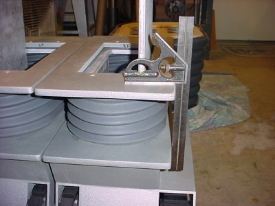
Next locating and securing the kneeplates. To align them directly above the lower plates I just used a square on each side.
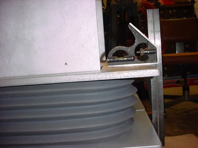
Vertically aligning from front and back.
I used 1/4-20 flathead screws and countersunk them into the tops of the kneeplates to sandwich everything together.
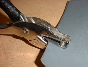
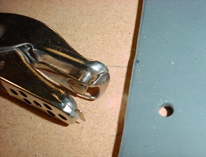
I used a paper punch to punch 1/4" holes in the silicone knees for the bolts to pass through. Makes a clean hole. This was a test on a scrap of the cutout. Marked the locations for the holes with kneeplates in position.
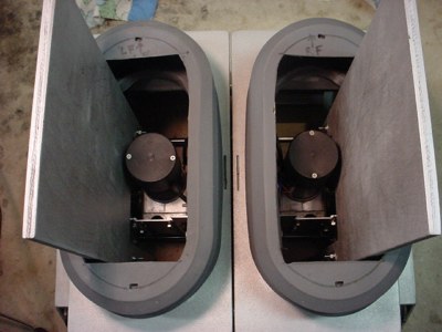
Both in place.
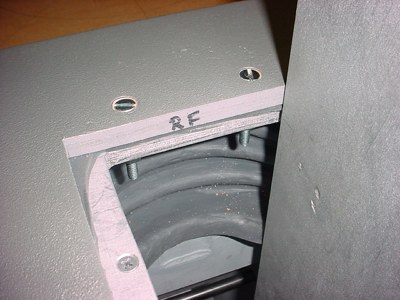
Here's an inside view where you can see the top of the knee sandwiched between the kneeplate and the internal support.
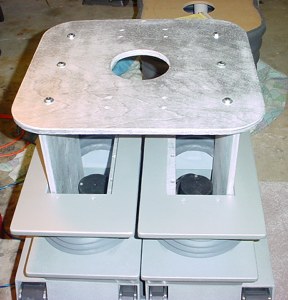
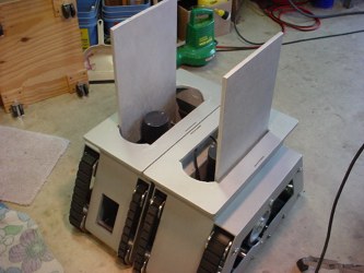
Next is the intermediate support plate that will hold the waist tilting components.
I cut two aluminum pieces of angle stock and mounted with 1/4" bolts to the top plate.
This needs to be removable for final assembly when the rubber legs are added. Also I used these angles here, instead of just screwing this piece to the supports, because more strength is needed here and it needs to be removable.
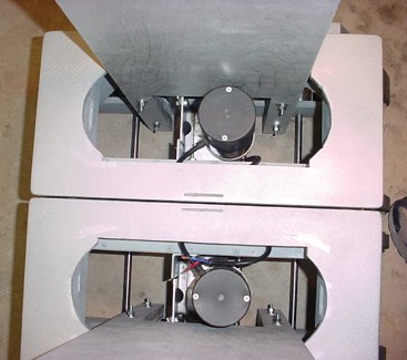
In position on the supports. I am using 3 bolts on each side to secure it. This ties everything together and stabilizes the assembly. Remains removable for rubber leg installation and future service. The main batteries will sit inside each leg section in this space.
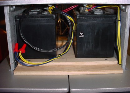
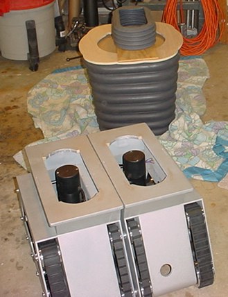
These are not the actual batteries I will be using, but some just for testing the treadseciton.
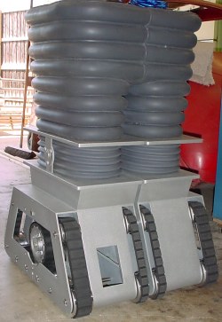
Here is a test fit of his new rubber legs. The next page "Leg & Hip Assembly" details the upper internal construction and the Hip actuation mechanism.