Bob's Lost In Space B9 Robot Project | home
Misc. Parts | Motor Shaft Extensions | Knees & Hinges | Treadsections | Tread Making | TreadMaking from Tires | Drive Parts | Drive & Tread Installation | Tread movie | Barry's Tread Movies | Drive Upgrade | Legs | Donut & Waist plate | First Stackup | Torso | Neon | Arms | Microphone & Knob | Chest Buttons | Power Pack | Torso Vents Misc | Making Vents | Large Vent Drawings | Arm Mechanism #1 | B9 Arm Mech Dev. | Wrists & Claws | Collar | Radar | Motorizing Ears | Making Sensors | Brain | Brain Cup & Light Rods | Bulbs & Wiring Diagrams | My Old Robots | B9 Builder's & Info Sites | Related Links | Building Reference Info | Parts Drawing Links | Site Revisions | Final Leg Assembly | Leg & Hip Assembly | Leg-Hip Action | Non-B9 Projects | 2008 TX BUILD-OFF | 2008 TX BUILD-OFF PAGE 2 | RoboCon 2009
Leg & Hip Assembly (Continued from Final Assembly)
I decided I wanted more strength in the support system, so I added vertical 1" aluminum angles to each of the supports.
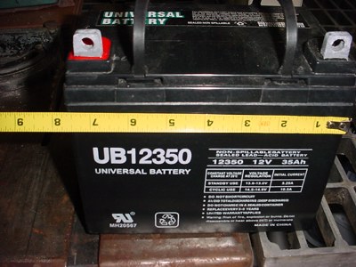
Here is one of the 35ah glass mat sealed batteries I am using.
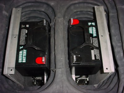
Both batteries sitting in place, not strapped in yet. My batteries sit above the knees, since I did not have room below.
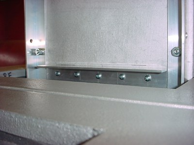
This is the lower battery mount on the support.
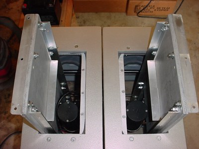
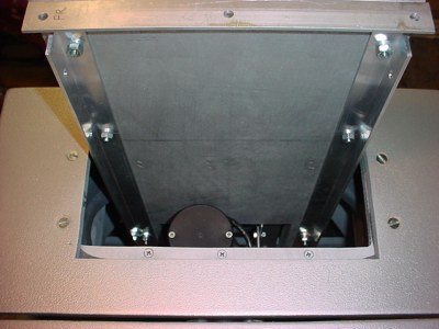
View of completed supports and angles. Note the top two angles for the mid section divider, I reversed them so the angles are outward now. This allows easier assembly to the hip section when the rubber legs are in place.
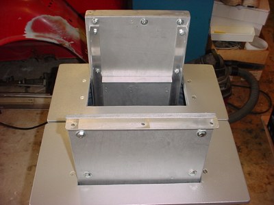
Another view of the angles mounted outward.
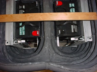
Batteries test fit. The wood piece is to keep the rubber legs spread during assembly. A real bearcat to work on alone. You need about 5 hands to put this together.
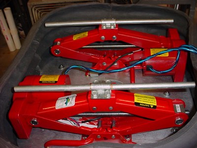
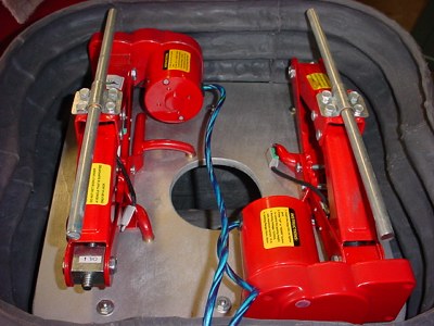
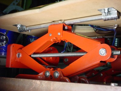
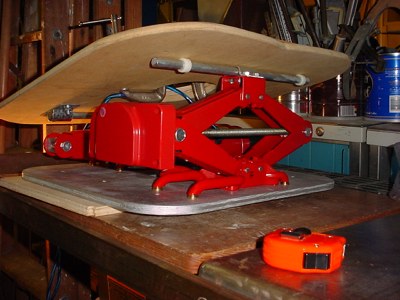
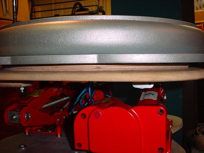
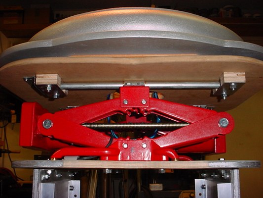
I wanted my robot to be able to lean forward and backward so I came up with a somewhat "off the shelf" way to do this. These are 12VDC electric car jacks. I bought these from Amazon.com after searching for best prices for $39.95 each. I did some investigation first to assure what my maximum width available was inside the rubber legs. I found there were a few electric jacks that were wider than these so I selected the narrowest ones. This saved a lot of from scratch construction on the hip assembly. I drilled 4 holes in the bases of each jack and used 1/4"-20 bolts to secure everything together.
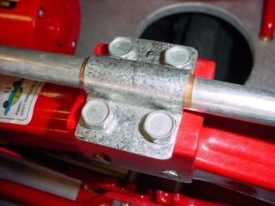
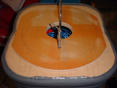
I mounted 1/2" aluminum rods on the top of the jacks. I first had to grind off the rivet holding the swivel bracket on top of the jack and remove that bracket. Then I made brackets from steel strips to hold the 1/2" rod which is for supporting my sub-waistplate assembly (Picked up the steel strips at Home Depot). This needs to be sturdy to support the full upper half of the robot (That is a copper shim under the bracket for a tight fit). Again all assembled with 1/4-20 bolts.
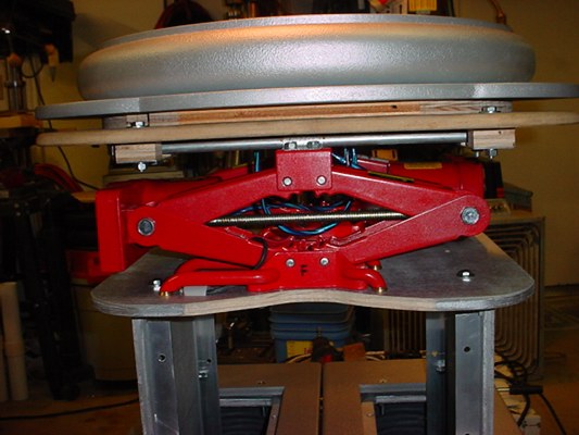
Side view.
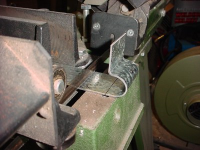
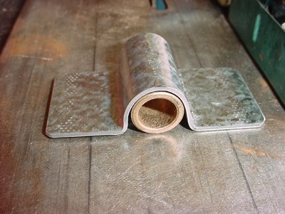
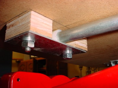
Next I had to make brackets for mounting the sub-waistplate assembly. I bent them around rod in my vice and cut to length after most of the forming.
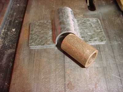
I made the brackets proper size to hold a bronze bushing that forms the bearing on the shaft. Picked up the bushings at Lowe's.
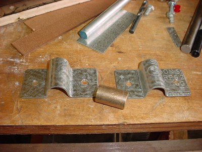
More bracket pics.
Ready to mount to the sub-waistplate.
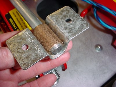
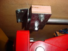
These are the "fixed" pivot side of the mech.
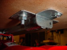
The other side requires a slide or ability to move forward and backward because "leaning" forward and back increases the length between the two rods. I used some nylon bushings and made a mount for them, see below. If you remember your right triangle geometry (a squared + b squared = c squared) you can actually figure out how much increase in length you need. I came up with about an inch. It's on a paper somewhere but not to bore you with that.

The sliding pivot mounts. The jacks come with lower and upper limit swiches. I am using the lower switches for all the way down as I scaled everything to support the legs at the lowest height I wanted them. The upper limit switches I removed from their mounting and I will be adding a new upper limit switch bracket for them on each jack (just haven't gotten that done yet).
I made them with just enough clearance to allow the bushing to turn for smooth operation and eliminate any binding.
I found some right angle brackets in my parts drawer to use as stops on the ends to keep things from shifting left or right.
Note the slider bracket is placed in just far enough to miss the motor gearbox when lowered all the way.
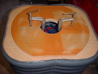
This is a spacer plate between my sub waistplate and the upper visible waistplate that holds the donut.
As it turns out 1/2" thick was just right to fit the top of my rubber legs between the sub waistplate and the upper one. (Remember, my legs were a reject set and the top of them was not fully formed, so I trimmed the top of them off leaving a ridge and it all fit perfectly. Sometimes you get lucky.
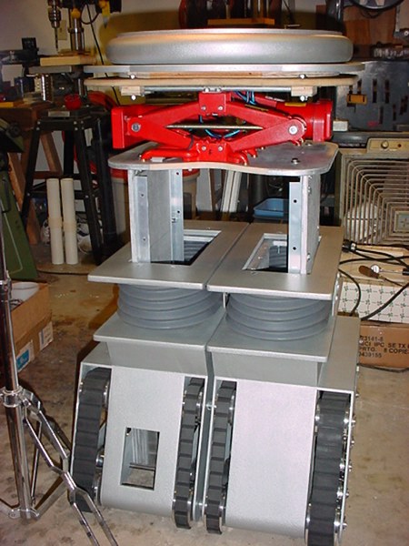
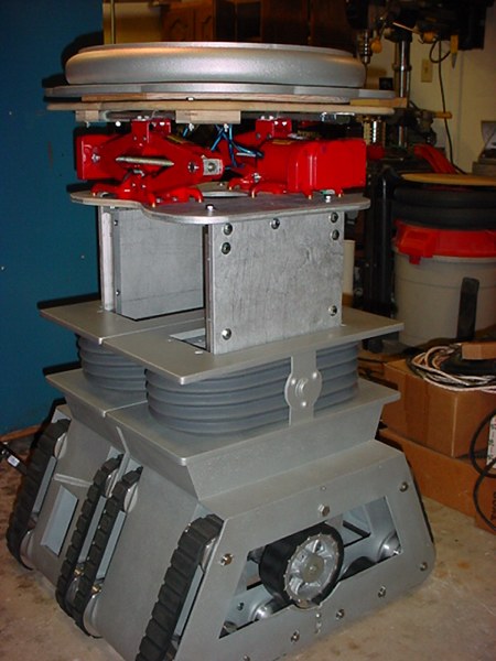
Here is the bare assembly.
Front with sliding pivots.
Notice I had to cut the center section on my midplate back to prevent interference with the legs in the crotch area. I did this on both the front and back of the midplate.
The next page shows the rubber legs installed and leaning with torso, plus some additional internal shots.