Bob's Lost In Space B9 Robot Project | home
Misc. Parts | Motor Shaft Extensions | Knees & Hinges | Treadsections | Tread Making | TreadMaking from Tires | Drive Parts | Drive & Tread Installation | Tread movie | Barry's Tread Movies | Drive Upgrade | Legs | Donut & Waist plate | First Stackup | Torso | Neon | Arms | Microphone & Knob | Chest Buttons | Power Pack | Torso Vents Misc | Making Vents | Large Vent Drawings | Arm Mechanism #1 | B9 Arm Mech Dev. | Wrists & Claws | Collar | Radar | Motorizing Ears | Making Sensors | Brain | Brain Cup & Light Rods | Bulbs & Wiring Diagrams | My Old Robots | B9 Builder's & Info Sites | Related Links | Building Reference Info | Parts Drawing Links | Site Revisions | Final Leg Assembly | Leg & Hip Assembly | Leg-Hip Action | Non-B9 Projects | 2008 TX BUILD-OFF | 2008 TX BUILD-OFF PAGE 2 | RoboCon 2009
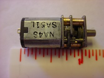
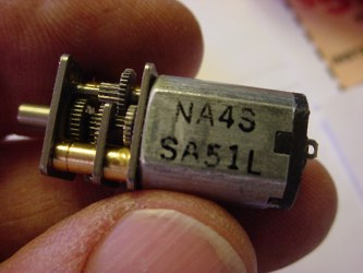
Some of the club members found a neat gear motor that will fit into the 1-1/4" diameter ball of the ears, so I though I would give it a try. I've been looking for a small motor like these. The motors are only $23 each, well worth prototyping these up to see what could be done with them.
Miniature Metal Gear Motor - 62 RPM
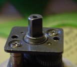
 This small 1.14" (29mm) by 0.47" (12mm) by 0.39" (10mm) motor features a high quality, all-metal 196.6:1 gear train for smooth, quiet operation and a long operating life even under harsh conditions.
The motor delivers 62 RPM with 46 in-oz torque (3300 cm-gm) while drawing an efficient 120ma at 5v DC. It weighs 0.29 oz (8.2 gram). It has a 3mm diameter "D" shaped output shaft. The shaft can be mated with most 1/8" hole output devices . The faceplate contains two mounting holes threaded for M1.7 machine screws such as M1.7 x 4mm machine screws.
Click on the link below:
They are available from HobbyEngineering
$23 each
They also have a 71 RPM that will work too. 71RPM for #19.99 each.
Either motor could also be used with a motor controller to vary the speed.
|
A few pictures. Very nice little motors!


- for the small motors
You need a plan for these, I used Craig Reinbrecht's drawing -
If you don't have it you can get it here Ear Posts& Ear Sensors
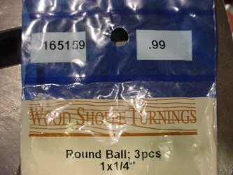
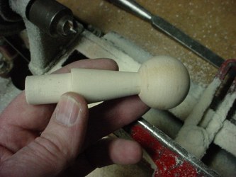
To use these motors I have to make my own Ear Posts. The easiest way I found was to start with 1-1/4" diameter wooden balls from the craft store. I got 3 for 99 cents. I bought two packs so I would have plenty of chances to practice on them. Be sure to get them without holes in them that are perfect spheres.
I also bought a length each of 7/8" & 5/8"diameter dowels.
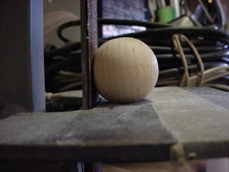
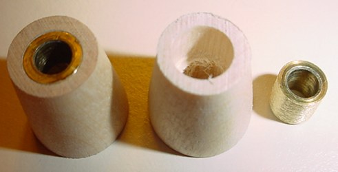
First thing to do is to create 2 flats on the ball at right angles to each other. Actually not too hard since the belt sander table is 90 degrees to the belt. You need to make each of these the same diameter as the portions of the ear post that will attach to them. I used 7/16" for the side ear post to fit up to and 5/8" on the top for the top portion of the sensor post.
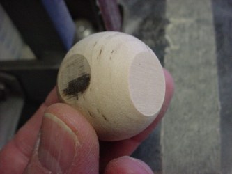
You can see the 7/16" on the left and the 5/8" on the top.
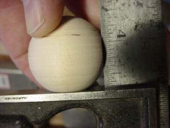
Looks good to me!
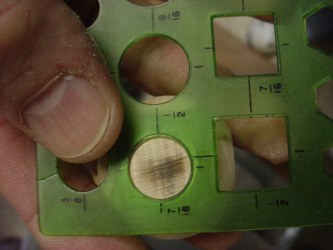
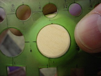
Next mark the centers on them. I used a circle template with cross hairs and marked them with a sharp pencil.
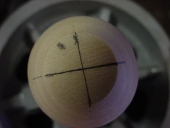
Ready for the drill press.
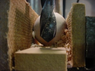
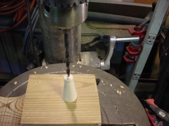
Set the depth stop on the drill press, as you will have to drill almost to the bottom of the sphere. I actually needed to go back later and drill lower than this picture shows. Note, I always use scrap wood blocks to protect the piece from the vise clamps. Plus you won't smash the wooden ball with them.
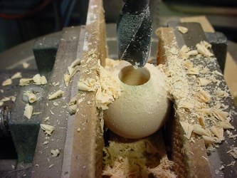
First I used a bit to fit the diameter of the motor body. I used a 31/64" bit.
Of course you do need a drill press and chuck that will take this size of bit.
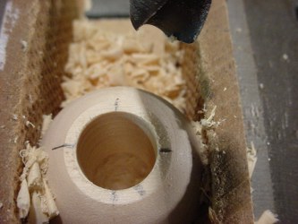
It is somewhat tricky to keep everything centered but these came out well. This was a new sharp bit.


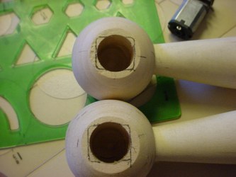
I used a 7/16" bit on the side hole. You can see in the left picture where the side hole intersects the top hole.
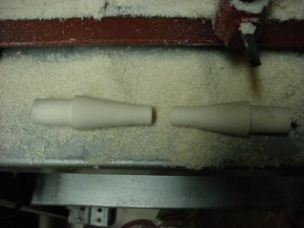
I turned the ear side posts on my wood lathe. For these I used the 7/8" dowel rod. I gave myself a full 1" long 5/8" diameter mounting shaft that will fit into my radar. Your radar may be different. I was having so much fun I forgot to take pictures while they were in the lathe before I cut them apart!
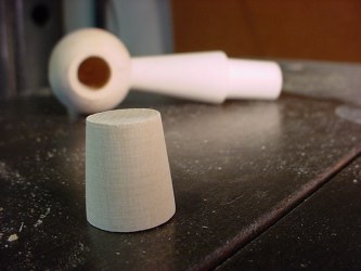
Also to attach the ear ball, I turned a 7/16" diameter end that will slip into the side hole in the ball.
Like so. I preferred to use the craft balls because turning a sphere is harder than it looks. Plus to make this all in one piece I would have needed to start with 1-1/4" or larger stock and that makes a lot more turning work out of it.
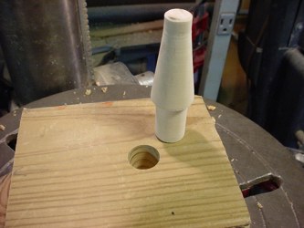
Drilled a 5/8" hole in a block to hold the sensor vertically on the drill press.
I used a 3/16" bit to drill a hole through the center for the wires.

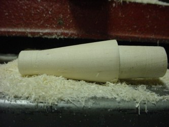
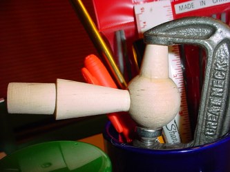
Next I turned the tops for the ear posts.

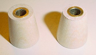
This is what they look like and how they fit up.
The whole ear post looks pretty good at this point. If you were not motorizing, a little glue, wood filler and paint and you would have a nice set of ears!
The gearbox on the motor is mounted within rectangular plates. So I marked them out and use a square file and my Dremel to take out the excess checking fit of motor as I went.
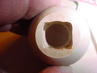
Here is how that worked out, you only have to go down inside by the dept of the gearbox.


Slip the motor in place.
Installing bushings for the sensor shaft.
I will be using 3/16" O.D. brass tubing for the shaft as it fits over the gearmotor shaft. Depending on what you have this may all vary.
First I drilled the top piece all the way through the center with a 15/64" bit which is somewhat larger than the 3/16" dia. I will be using for the sensor shaft, but smaller than the O.D. of the bushing. The bronze bushing I found in my junk box and cut it in half on the bandsaw so I'd have two. Then I selected a bit and countersunk the hole for the bushing. It was too tight a fit, would have split the wood (and my next size drill bit was too big) so I sanded down the O.D. of the bushing until it fit perfectly and snugly. Actually I put it on the 3/16" shaft and used the emery belt sander to spin sand it evenly.
Here they are finished. Actually it took ruining the first two to make these. I drilled one of the holes off center in one of the originals and then countersunk too large a hole so the bushing didn't fit snug. What do they say, measure once, cut twice! When working with wood you also have the wood grain to contend with that can easily throw you off center. I don't have a lathe I can chuck parts like these into to drill a perfect center hole, so doing it on the drill press is somewhat difficult. But wood is cheap and easy overall. You can get very good results with a little practice.
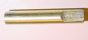
Here is the brass tubing for the drive shafts. This is made up of 2 pieces, one 5/32" dia nested inside one 3/16" dia. The 5/32" just fits over the motor shaft. First I cut them to length, deburred them, cleaned, fluxed and soldered them together with my torch. I ground the flat on the end of it for the sensor holder screw to hold it.
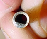
Then I held it horizontally in the vise, fluxed it and pooled a small amount of solder into the end of it. Then filed with a small flat file to create the "D" shape to fit over the motor shaft. This way it will slip snugly over the motor shaft without any fasteners and I will be able to remove it if necessary.
I wired the motor using stranded 24 ga. twisted pair wire. I dry assembled everything first and tested the operation with the drive shaft and sensor in place. I used three 1.5 volt batteries. 4.5 volts gives a nice speed. This also assures getting the right alignment of the top cone onto the ball. Made initial markings.
To assemble I started by threading the wire through the ball and fitting the motor into it. I did have to use the Dremel to carve a spot for the wire inside. Next I threaded the wire through the side post and glued the side post into the ball. Lastly I used the drive shaft to align the top cone, marked its location carefully and sparingly wood glued it to the ball (careful with the glue not to get it oozing inside into the motor. Removed the drive shaft being careful not to move anything, clamped it and smoothed a bead of glue around the edge so it will soak in.
Last to come I will put some wood filler around the seams, texture and paint. I'll drop in some pictures of it finished when the weather gets nice enough to paint.
or
see below the beginnings of use of right angle geared ears.
The following section will be for right angle geared ears:
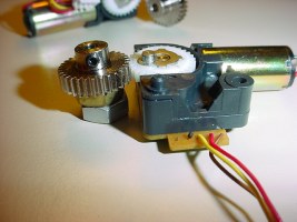
I was originally going to install geared ear posts on my radar, so I needed motors to drive them. Here is what I came up with. I may use the geared ears on my stunt robot instead of my main robot, I haven't decided yet.
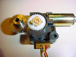
These were surplus motors I acquired from All Electronics, although they no longer have them. Some looking around and you can find others in various voltages, rpm, etc. I'll post the specs on these later on.
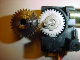
These motors and drive gears will mount under the radar to power each ear. One motor for each ear.
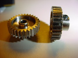


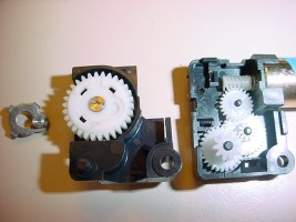

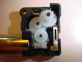
I will be following up with info and pictures of the gears, shafts, sleeve bearings, etc. for the construction process on my geared ears.
TO BE CONTINUED