Bob's Lost In Space B9 Robot Project | home
Misc. Parts | Motor Shaft Extensions | Knees & Hinges | Treadsections | Tread Making | TreadMaking from Tires | Drive Parts | Drive & Tread Installation | Tread movie | Barry's Tread Movies | Drive Upgrade | Legs | Donut & Waist plate | First Stackup | Torso | Neon | Arms | Microphone & Knob | Chest Buttons | Power Pack | Torso Vents Misc | Making Vents | Large Vent Drawings | Arm Mechanism #1 | B9 Arm Mech Dev. | Wrists & Claws | Collar | Radar | Motorizing Ears | Making Sensors | Brain | Brain Cup & Light Rods | Bulbs & Wiring Diagrams | My Old Robots | B9 Builder's & Info Sites | Related Links | Building Reference Info | Parts Drawing Links | Site Revisions | Final Leg Assembly | Leg & Hip Assembly | Leg-Hip Action | Non-B9 Projects | 2008 TX BUILD-OFF | 2008 TX BUILD-OFF PAGE 2 | RoboCon 2009
Misc. Parts
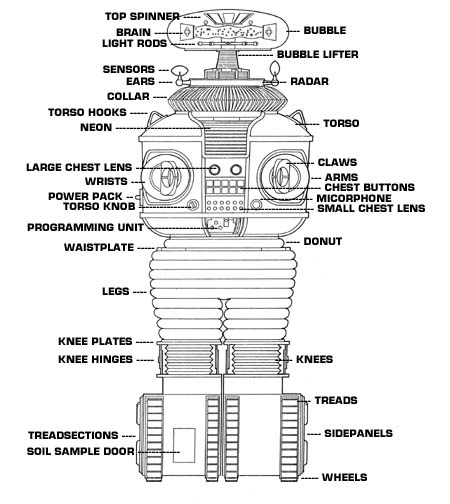
I'm not sure of the origin of this drawing, but it shows what the robot parts are commonly named. Not necessarily to scale or completely accurate drawing.
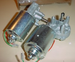
Dewert Heavy Duty Motors
These motors have been used successfully by other members for torso rotation, treadsection drives, bubble lifter, arms and hip animation. Extremely versitle. Unfortunately they are no longer directly availiable from Dewert (2007). Now in limited quantity at Surplus Center, see below for link.
MOTOR SPECS:
Original Part Number 000.002.016
19 rpm @ 12v
35 rpm @ 24v
Motor shaft diameter 10mm. (This is slightly larger than a 3/8 diameter hole, you can drill or ream out a 3/8 hole to fit the shaft when attaching pulleys, hubs or extensions.)
Takes 3 Mounting bolts: Metric M6 x 16, 1.00 pitch (6mm dia x 16mm long threads)
Current draw: 1-2Amps, very low startup current.
|
LIMITED QUANTITIES
 Item# 5-1632
Price $19.99
221 In Stock 7-7-07
Only 148 in Stock as of 1-15-08
Only 51 in stock as of 8-10-08
|
These motors were used in the Arm Mechanism #1 shown on this site.
Unfortunately as the last few years have gone by, the sources for these have dried up.
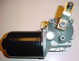
Surplus Windshield Wiper motors Used To be available from these companies:
I check their sites occasionally. Surplus stuff is a lot cheaper than new but always limited quantities and changing.
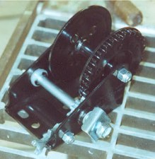
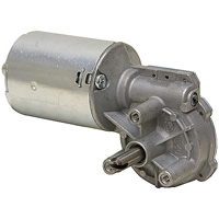
This is one of 2 winches that I was going to use to make my final tread drive pulleys from. FYI the gearing is 3:1. As it turns out, I am not using these now that I have custom made my own sprockets. In fact now, I am upgrading the drive to wheelchair motors.
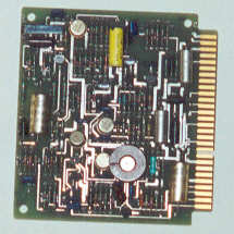
Old circuit board, possible power pack with some modification? Cut to size, add a frame, phono plugs & some acrylic -wal-la instant power pack. I know it's not exactly like the original, but who would know? And this one was free. We'll see, I may end up making one like the original anyway. (See my power pack page, I am actually now using a nice reproduction of the original pcb).
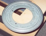
9" lazy susan for radar from local hardware store for radar.
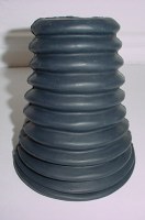
An older bubble lifter boot made similar to the original robot's that I obtained through the club.
There are no exact answers on the height of the neck and bubble lifter over the radar. . I looked at my set of Dave Painter's prints and they don't really show it in detail.
My estimation is that the max height would be about 5 to 6" in height extended and maybe a minimum of 3" high compressed. That's 3" of travel max. Most of the height issue is personal choice from looking at the photos and screen grabs of the robot. You really need to do the radar, ears and sensors to be sure how you will want yours. I didn't realize until I put the sensors on that the yellow tall one would create the low end limit for the bubble lifter/neck compressed. You could do some scaling off photos of the real robot from the club site photo libraries, but what looks good is all you really need for the height.
The boot above measures 4" O.D. at the bottom and 3" O.D. at the top of the 9th ridge. A lot of guys are concerned over the number of ridges (or peaks) on the boot-I believe you can count that 9 is the correct number from photos.
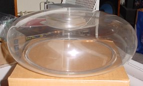
The bubble, I purchased it several years ago from Planet Plastics. They are out of the business of bubbles. The plastic is slightly foggy rather than crystal clear, I don't know if it is superficial or will polish out or not. It is fairly thick and solid. Some club members are working on a method to make their own and there is documentation on the clubsite on one method. I've heard the only other bubble currently available in 07, although very clear and made from some sort of aircraft plastic, is quite thin and will even flex some.
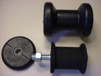
Originally, I needed to make 2 idler wheels to use to tighten the 2" treads with my first V belt drive. I am using these currently at the top of the treadsections. The rubber boat trailer spool roller above was modified by cutting the ends off with a hacksaw in my little wood lathe and using coarse files to reshape the center to fit the tread. You end up with two 1/2" thick rubber wheels cut off from the ends-maybe one for rotating the torso?
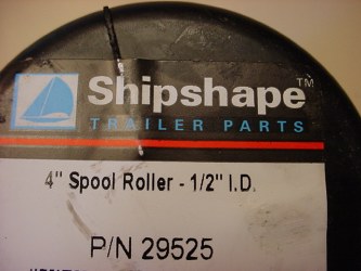
Here is the actual tag with part number. These wheels have a nylon center sleeve with 1/2" inside diameter. I got them at our local Northern Tool Co., but I couldn't find them on thier website.
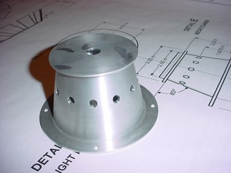
The aluminum Brain Cup.
An older version that was available through the club & since I do not have a metal lathe, or the expertise to do it I decided to buy this part.
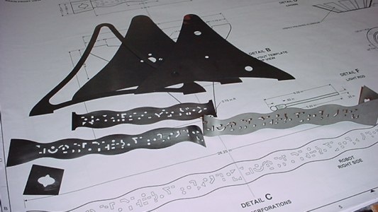
This is an older Brain kit I acquired second hand, originally available through the club. A few problems were enountered here with forming the pieces for assembly by the original owner, but I can work those out. At least now I do not have to cut out all those little holes by hand. I will be taking pictures of the soldering assembly and repair of this.
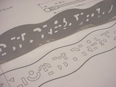
Close up of the cutouts.
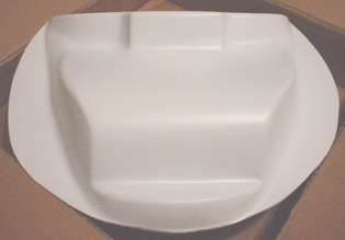
Neon Backplate vacuformed from styrene plastic. Originally available through the club.
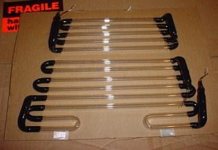
Real Neon. An older version.
It is constructed in 2 pieces since it has to fit the opening in the torso. Available through the club.
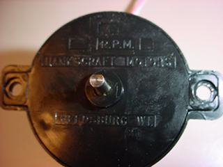
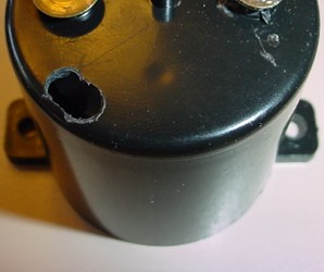
Below is the Hankscraft motor many have used to turn the top spinner (crown) and actuate the light rods. It fits into a club made neck bracket/bubble support which I am not using. I am going to use an alternate motor and neck bracket made from PVC parts.
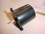
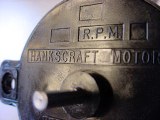
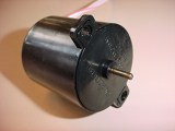
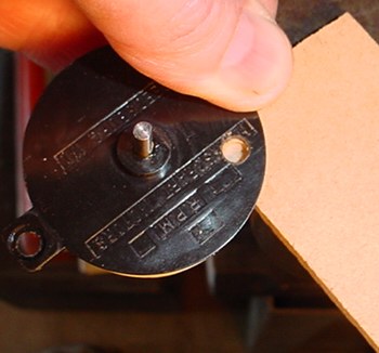
This one operates on 6 VDC and turns at approximately 6 RPM. Not as powerful as a 12 VDC version but is workable.
 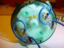 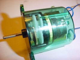 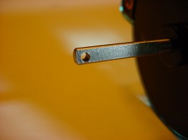 6 RPM 12 VDC permanent magnet. Reversible. Sleeve bearings. This is a low torque clock/hobby type motor. No-load speed at 12 VDC input is 12 rpm. No-load current is 0.001 amp. With 4 oz-in load rpm is 6 @ 0.008 amp. Shaft: 1/8" dia. x 3/4" long with a 1/16" cross drilled hole located at the end of the shaft. A flat extends 5/8" along the shaft. There are two ear style mounting tabs on the face of the gearbox which have 1/8" clear mounting holes. Dimensions: Motor body is 45mm dia. x 2" long (excluding shaft). The width across the mounting tabs is 2-7/16" nom. The motor has 3" wire leads. There are also Fanhestock style clips mounted on the rear for optional motor connections.
|
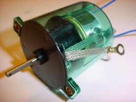
This one is another motor I found at C&H surplus who is now out of business, excellent price ($4.95), I hate to see them gone. I guess thier prices were just a little too good. It is 12VDC, includes internal motor shielding and supression capacitors and external grounding lead. It has twice the power as the 6 volt motor and may help eliminate any electrical noise into other systems in the robot. It is the same size and construction as a Hankscraft motor, but does not say Hankscraft on it. I've not been able to find another source for it.
Try this - but Be Careful -Enter at your own risk!
Disassembly of your Hankscraft motor required-It's plastic case is somewhat fragile.
Also, Hankscraft motors may not all be identical internally.
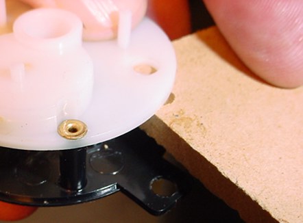
I drilled out the rivets that hold together the case. Be careful, this isn't the strongest plastic.
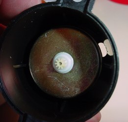
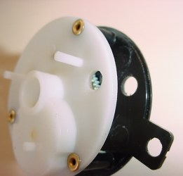
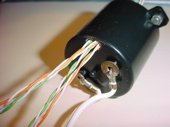
Drill a hole in the bottom of the case from the backside and be careful not to hit the motor inside. I drilled a couple holes to make an oblong hole to give a little more space past the side of the motor. Then drill holes holes through the geartrain assembly. Be sure to check the alignment when assembled, there is only one side of the geartrain with space for holes to be drilled.
Be sure to support each of the sections of the assembly so you don't break it with drill pressure. I used a variable speed drill.
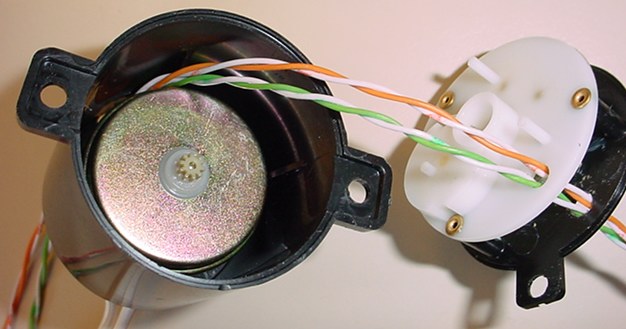
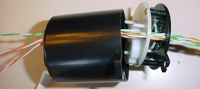
I easily fed 8 wires through. This is 22 gauge wire from a Cat. 5 cable.
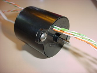
Use some small screws and nuts to reassemble the motor where the original rivets were.
Of course you will have to orient the motor properly in the brain cup so the wires are toward the back half of the cup out of the way of the light rod ends.
You may have to drill a hole inside the base of your "neck" bracket toward the inside edge of it to feed the wires through if you are using one of the club type aluminum ones.
Go to Motor Shaft Extensions