Bob's Lost In Space B9 Robot Project | home
Misc. Parts | Motor Shaft Extensions | Knees & Hinges | Treadsections | Tread Making | TreadMaking from Tires | Drive Parts | Drive & Tread Installation | Tread movie | Barry's Tread Movies | Drive Upgrade | Legs | Donut & Waist plate | First Stackup | Torso | Neon | Arms | Microphone & Knob | Chest Buttons | Power Pack | Torso Vents Misc | Making Vents | Large Vent Drawings | Arm Mechanism #1 | B9 Arm Mech Dev. | Wrists & Claws | Collar | Radar | Motorizing Ears | Making Sensors | Brain | Brain Cup & Light Rods | Bulbs & Wiring Diagrams | My Old Robots | B9 Builder's & Info Sites | Related Links | Building Reference Info | Parts Drawing Links | Site Revisions | Final Leg Assembly | Leg & Hip Assembly | Leg-Hip Action | Non-B9 Projects | 2008 TX BUILD-OFF | 2008 TX BUILD-OFF PAGE 2 | RoboCon 2009
Torso
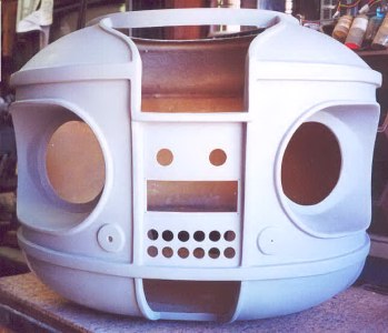
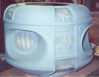
This is my fiberglass Torso.
It is heavy duty and will finish up nicely, now that's real 'body work'.
I have cut out all the large holes, I used my variable speed jigsaw with a fine tooth metal blade at a medium speed. I went through 2 blades, fiberglass is hard on them, I cut close to the edge and filed the edges smooth on all the openings. There are still many small holes to drill for the chest lights, mic, knob, power pack and torso hooks, and to cut the opening for the chest buttons. Save those cutout fiberglass pieces, to test drilling, painting and texturing methods on-you'll be glad you did. (Torso from club member Rod Rickenbach.)
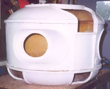
You can see at the trim edges where the seams in the mold came together will require bondo and sanding. This torso was from a four piece mold, top dome, bottom dome, front half and back half.
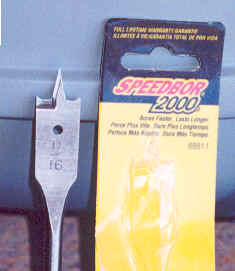
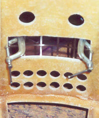
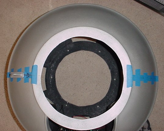
Next I had to drill the 14 light holes, one of the scariest tasks for anyone building a B9.
I found these Speedbor 2000 bits at Home Depot and they have cutting points on the outer edges of the bit.
I highly recommend that you use only new bits and they must have the cutting points on the outer edges of the bit. They're relatively inexpensive and you'll need 11/16" dia. and 1" dia. bits for the lights.
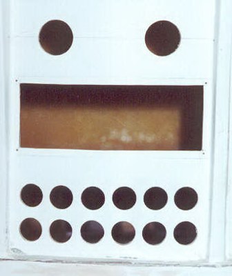
I measured and marked out with a sharp pencil the layout of the holes I decided to use. Then very carefully center punched each hole location. There are two or three variations of the layout that have been used on the reproductions. Use the one you prefer.
Practice drilling on a scrap of fiberglass cut from one of the vent or arm hole areas first.
I used the Speedbor 2000 bits in a variable speed drill at a slower speed. Cut from the front of the torso first to get the hole and its outer edges started, but don't drill through yet. Then go inside the torso and use the center hole you've just drilled to get the hole and outer edges started from the inside. This prevents any splitting out of the fiberglass. Then go back to the front of the torso and finish drilling through. Use just enough speed and pressure to cut the fiberglass and you should end up with a very clean hole as if it was machined. If you did it right you'll also end up with a bunch of fiberglass washers!
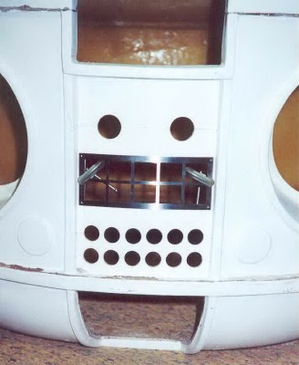
Here is a shot of the bezel clamped to the opening I cutout with my jigsaw. (Bezel by member Scott Sanderson). This will allow me to precisely mark the holes for the number 0 (zero) screws that are used to mount the bezel. I obtained 0 x1/2" stainless screws and nuts from a local hardware store (No-Home Depot doesn't carry them!). Be sure to position the bezel right side up, as the vertical edges need to follow the taper of the torso trim.
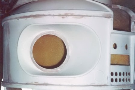
Inside shot.
Now I'm getting that Bondo work done on the seams and defects. I takes several thin coats shaping between each coat. I used 80 & 100 grit for the real rough work on the first coat or two and 150 grit mostly for the final shaping. Getting the trim edges straight takes some patience and a wood backing block. Then sand it with some 220 to smooth everything out.
After you think you have it looking good with the Bondo sanded, give it a coat of primer and anything you've missed will show up.
I sanded the primer with 220 grit and gave it another coat of primer and sanded with 320. A couple of touch ups here and there and its ready for the last coat of primer before I texture it. I'm not drilling the holes for the power pack and torso hooks until I have made those parts and they're ready to mount. That way the holes will be sure to line up. I did paint the inside black as you'll see in the next photo.
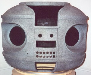
Here is the texture, I used the same as on the treadsections: plasti-kote - Fleck Stone - Faux Granite Base Coat. You have to spray it at 90 degrees to the surface you want textured. Each edge of trim, etc. needs to be sprayed at 90 degrees with short spays to get it even. Be sure not to touch it, stays wet a long time, dry time at least 24 hours. It came out so even that I'm only doing one coat. It looks pretty neat just like this, before sanding, but much more to finish.
Texture sanded with 150 and another coat of primer to seal it and see how it looks. Then sanded again with 220 to even it out more. Then another coat of primer and sanded with 320.
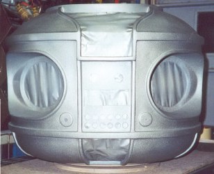
Here's a larger image of the torso with the first coat of 1978 Alfa Romeo silver, you can see the texture in this photo. Again this will get sanded with 320 to smooth a little more.
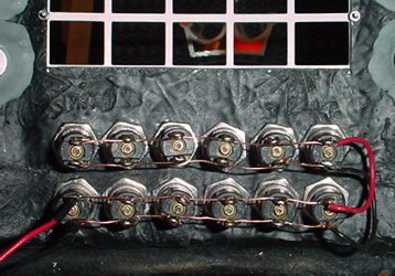
Belly lights wiring.
Simple, wired all in parallel since I am using flashing bulbs.
I just used two continuous pieces of bare conductors, wrapped around each terminal and soldered.
Two insulated jumpers to connect top to bottom row and black and red connecting leads (lower left).
12 volt power to them and they are ready to go.
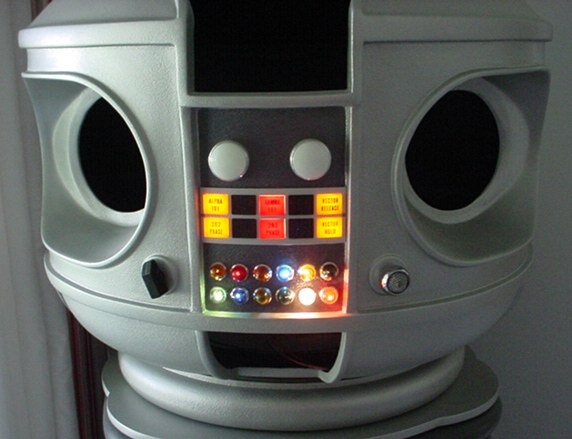
He's got his Alfa Romeo paint now and is looking better and better. The center section was painted with Duplicolor Gunmetal T177.
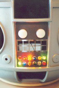
The chest lights, belly lights and bezel have been installed and look great. (The two large chest light reproductions were from club member Dewey Howard, repos no longer available on these-originals are now available by special order through the club, by Dennis Wilbur.)
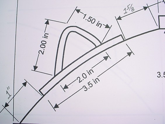
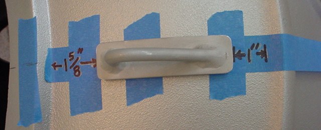
Original Dave Painter Blueprint-note hook shape & positioning not completely accurate.
The original assumption was that the hook mounting base is vertically centered on the top dome of the torso.
Assuming the mounting base of your torso hook is 3-1/2" in length, that would put it 1-5/16" down from where the top dome of the torso meets the neck ring and 1-5/16" up from where the dome meets the upper trim ring. Craig Reinbrecht later compared front photos and determined that 1-5/8" down from the top & 1" up from the bottom was more accurate.
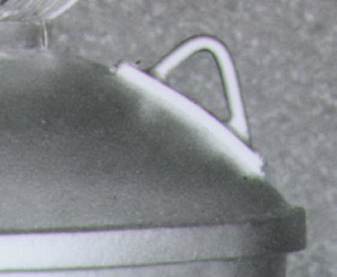
Here is an original robot reference picture courtesy of Craig Reinbrecht. It shows the correct positioning.
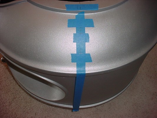
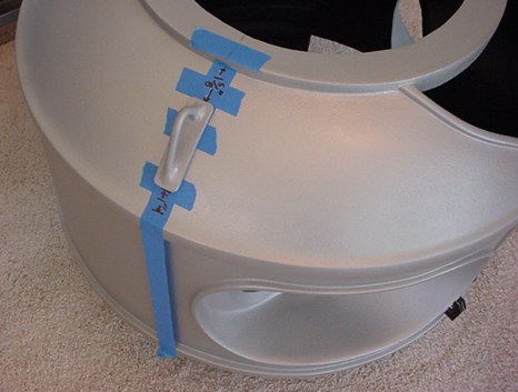
Next is to layout the proper location for the hooks.
I used 1" wide painter's tape to layout the position.
My torso is not perfectly round, so the layout took some patience.
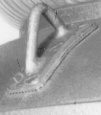
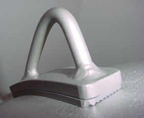
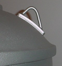
This shows the position. I am using Jerry Chevalier's torso hooks.
I was always going to make them from scratch, but when Jerry gave these away as door gifts at one of his "Texas Buildoff's" why make them! I did round the corners of them to match more like the originals.
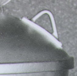
Just another view.
The original robot seemed to have a rubber type gasket or spacer under the torso hooks.
It was ribbed on the bottom side. Thanks to Bill Kendzierski for the photo.
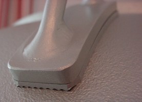
You can see the six flathead screws in this photo also, but I am not doing those as there is not room for them the way my torso hooks are made. Also note the rounded corners.
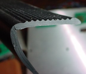
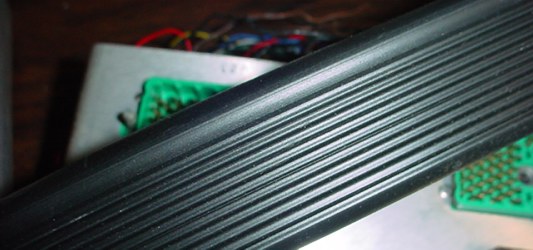
I found some vinyl stair edging that had ribs on one side and flat on the other to make the rubber like spacers to go under the torso hooks as seen in original torso pictures. Found it at Home Depot in the tile and flooring area.
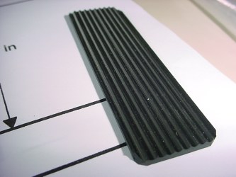
I cut pieces to fit each torso hook.
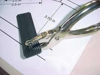
And used a paper punch to punch holes for the mounting screws that hold the hooks to the torso.
I painted the edges and top of them with the same torso paint.
Painted the torso hooks same color as torso too.
Here is a look at the gaskets in place. I may or may not keep the gaskets, it is a cleaner look without them.
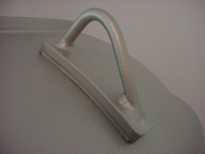
Another view.
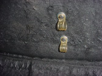
Inside the torso, the two mounting screws for the torso hook.
I also added some wire retainers to the screws to use when wiring the internals.
Comparison photo with the gasket. Mine on left, original on right.
Not exact, but if you don't have the picture then you never know.
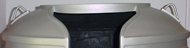
Both in place. They look very good!
Go to Arms
Go to Michrophone & Knob
Go to Torso Vents Research
Go to Making Vents