Bob's Lost In Space B9 Robot Project | home
Misc. Parts | Motor Shaft Extensions | Knees & Hinges | Treadsections | Tread Making | TreadMaking from Tires | Drive Parts | Drive & Tread Installation | Tread movie | Barry's Tread Movies | Drive Upgrade | Legs | Donut & Waist plate | First Stackup | Torso | Neon | Arms | Microphone & Knob | Chest Buttons | Power Pack | Torso Vents Misc | Making Vents | Large Vent Drawings | Arm Mechanism #1 | B9 Arm Mech Dev. | Wrists & Claws | Collar | Radar | Motorizing Ears | Making Sensors | Brain | Brain Cup & Light Rods | Bulbs & Wiring Diagrams | My Old Robots | B9 Builder's & Info Sites | Related Links | Building Reference Info | Parts Drawing Links | Site Revisions | Final Leg Assembly | Leg & Hip Assembly | Leg-Hip Action | Non-B9 Projects | 2008 TX BUILD-OFF | 2008 TX BUILD-OFF PAGE 2 | RoboCon 2009
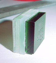
First off I found 10 lighted 1" square pushbuttons for $3.45 each. And of course they are surplus so they may not be available forever. From my favorite surplus place All Electronics. Most B9'ers know that the chest buttons were not square, but rectangular, but these are just to provide the operation and lighting from behind the chest bezel with the actual size and color button fronts.
Click on link below to go to All Electronics
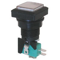 Momentary-action, S.P.D.T lighted pushbutton switch for displays and games. The rugged snap-action switch assembly is designed for millions of operations. White 1" square polycarbonate lens. Rated 5 Amps @ 125/250 Vac. The assembly is lighted with a replaceable 12 Volt, 3 Watt, #161 wedge-base lamp. Matte black plastic 1.29" diameter x 0.13" high bezel. Top of switch sits in a 1.1" recessed square which prevents rotation. 0.93" diameter threaded bushing with a plastic nut mounts in panels up to 0.70" thick. See spec sheet for mechanical drawings.
|
See notes near bottom of this page for general info on using "momentary" switches.
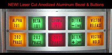
For the Bezel and front buttons, I am now using Craig Reinbrecht's new reproductions. They are excellent and available on the clubsite vendor listings.
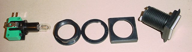
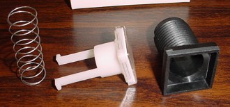
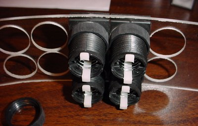
The first thing I did was to disassemble the switch and toss the 'huge' square backer plate and the large washer.
Note, the bulbs will be replaced with LED versions to eliminate the heat from the incandesent bulbs. See notes further down on this page.
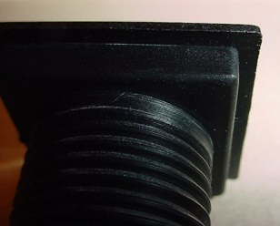
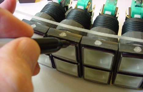
You can see from the backside of the switch how the outer bezel protrudes way beyond the switch enclosure itself. This has to go to be able to fit the switches close enough together behind the bezel.
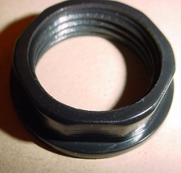
Same goes for the nut, it will have to be ground down.
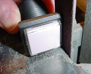
Here it is on the 1" emery belt sander using an 80 grit belt sanding off the excess edges. Just beware with these switches and the modifications of sanding them down, you have to be patient and have a steady hand and take
your time lest you sand your fingers or ruin the switch itself!
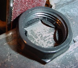
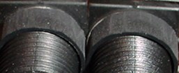
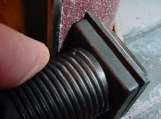
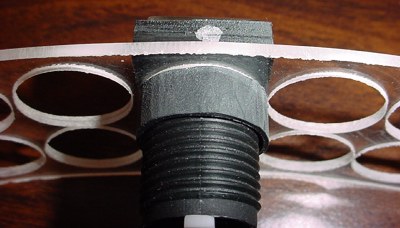
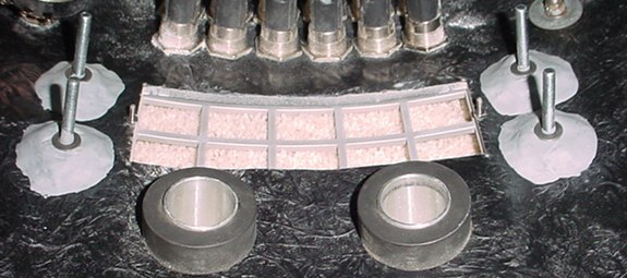
Same goes for the nuts. They actually have to get sanded down quite thin. You can see in the second picture here that they need to be thin to fit close together.
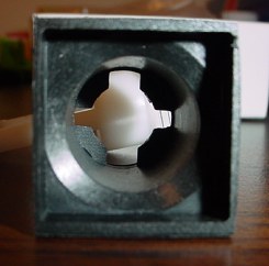
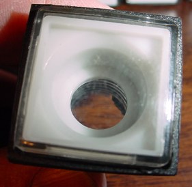
I had to sand the walls on 3 sides of the switches down to about 1/2 of their original thickness to get the switches to set close enough toghther to fit behind the bezel and to stack properly 2 high. You can see I removed the center guts here.
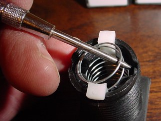
By carefully removing the spring from behind its retainers, you can 'unscrew' it out of the assembly to remove it.
You do need to disassemble it to remove the built in diffuser. This diffuser will interfere with the proper color of the reproduction buttons. Craig provides the proper diffusers with his buttons and they will be mounted as part of the switch button front outside of this switch assembly.
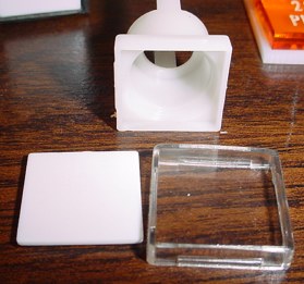
This is what the inner parts look like.
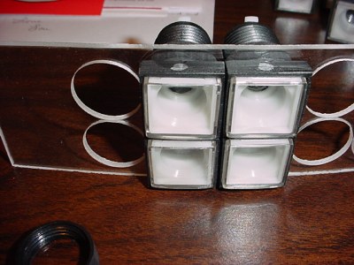
Re-assemble the switch without the diffuser, just using the clear front.
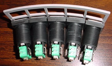
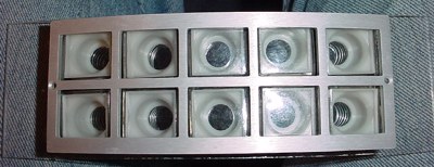
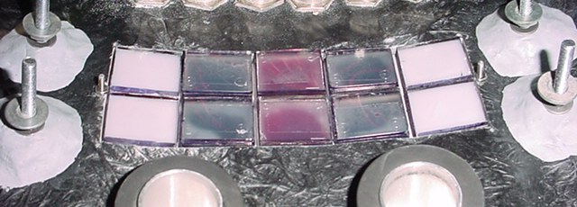
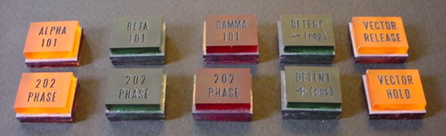
This is how they line up behind the bezel.
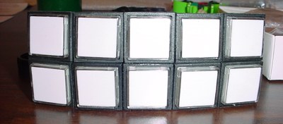
Just a stack up of them.
Another lineup behind the bezel.
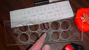
Making of the backer plate to hold the switches. Using the speedbor type bits to drill the 1" holes. Half way through 1/8" acrylic and then turn over and drill through. Just like drilling holes in the torso as my club fellow builder, Jim Rauch, reminded me as he was experimenting with these switches at the same time I was.
If you want a template to make one of these here you go, a pdf file. Click on this link to download below. I used the template to mark the centers of all the holes, they are very close, so you want to be accurate.
or here is the drawing
Not bad for an amateur.
Using some fine emery paper to smooth the edges. That's my paper template in the background.
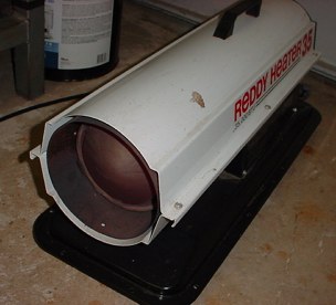
Since my heater was heating the garage anyway, I used it to heat the plastic backer plate to form it to the right radius to fit the torso.
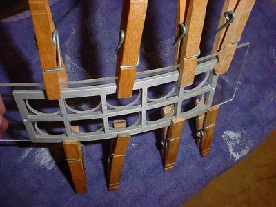
I just heated the plastic plate and formed it to fit Craig's aluminum bezel as a template. Clamped it until it cooled.
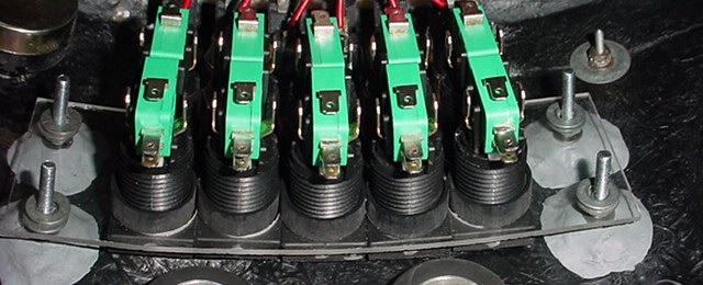
Install the switches in the backer plate. I started in the center because this is a tight assembly and there is not much room for your fingers while assembling it. Finger tight on these nuts is plenty. Note how thin they had to be ground to fit. Also note that I marked to top of the switches so I did not install them wrong. When you go to install the micro switch/light assembly they have to be in the proper postion. Also I didn't grind down the top of the switch, only the centers that mate against the bottom row of switches.
Adding more in place.
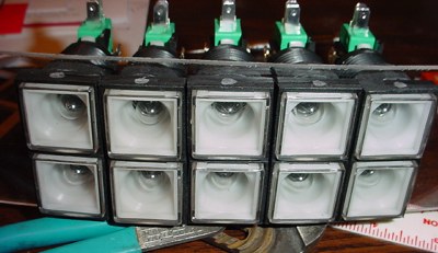
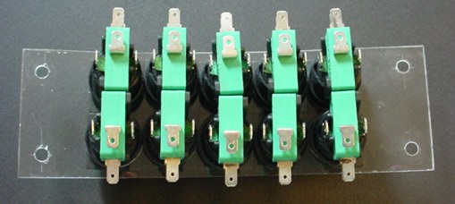
Buttons all installed, switches snapped into the back.
Just a top view. Note my top dots for assembly convienence.
The bezel sitting on top to see fit up.
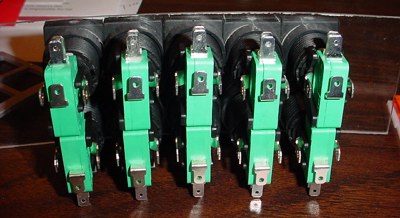
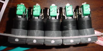
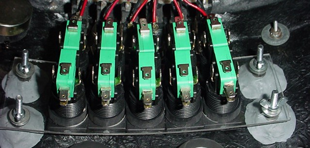
Nice back view of the actual switch portion of the assembly. As close as they can possibly get.
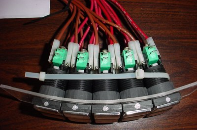
These are not the final wires for the lights, just ones I had with quick connects on them for a try out of the lights. You can see here that the light connections are on either side of each switch.
Now these will have the brightness I am looking for.
My robot must walk, move, talk and his lights must be BRIGHT!
#161 T-3 1/4 incandescent bulbs.
From Allied Electronics
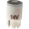
These are the LEDs that take the place of the 161 incandescent bulbs.
SloanLED Lamp; WEDGE BASE LED, T-3 1/4, 14V, PURE WHITE
Allied Stk # 265-5707, Mfr's Part # 516-147, $7.51 each.
Notes on Momentary Switch use:
The 12volt lights are separately powered from the switch. As they come there are no interlocks as some lighted push buttons have. Truly just a momentary switch. (Some switches internally switch on/off their own light or led and remain on when pushed once, and then when pushed again the sw releases and turns off and they can be pricey.)
If you want the light in these switches to go on and off by pushing the switch you will have to design that into the external control circuit in addition to whatever you want the switch to control. There are several ways to do all of that, with electronics or even with relays.
Coming up with 10 different things to do with them may be a lot anyway. You could for instance set up pairs of 5 switches for 5 functions, push one that latches on a relay and turns on a function and the one next to it or below it when pushed would de-energize the relay and turn off the function.
You would need a 2PDT relay to do this for each pair of switches, 1 pole latches on the relay & energizes that pair of
switch lights and 1 pole controls whatever robot function you want. I am going a little more sophisticated than that and having one relay for each of 9 of the switches.
Or you could just power the lights separately and not really have the switches control anything.
Relays are simple and relatively cheap if all you want is to turn a few things on and off. With relays you can't easily change the functions without rewiring as you could do with a programmable or electronic controller board.
I am using old style relays and sockets and hard wiring them. This old technology tends to take up a lot of space with the ones I am using.
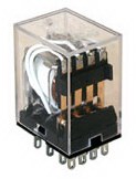
4PDT Relays 12VDC coil = CAT# 4PRLY-12
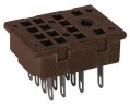
14 PIN RELAY SOCKET CAT# PRLY-S
(Note - socket retainers are not available, and sockets will be expoxied in place.)
Bezel installed with switch assembly test fitted behind. Notice how close the bezel mounting screws are to the switches behind them.
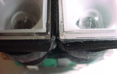
I had to round the corners of the switch housings on the ends to allow the bezel screws to clear them.
You can see the 4 holes I located and drilled for mounting the switch assembly in the corners of the plastic mounting plate. When previously test fitting the assembly into the torso I marked locations that would work in the torso so I knew I had a good place to mount the screws to the torso. Also you will want the holes to be 'clearance' holes larger than the screws you are using, since the torso is rounded ends of the screws will be closer together than where the assembly sits and you will need to be able to install without bending the switch assembly.
Next I mounted 4 flat head 10-32 screws to mount the bezel assembly. I used Craig's method of first using 5 minute epoxy to glue the flathead screws into place and then plumbers epoxy around them. The method is detailed on the clubsite construction tips.
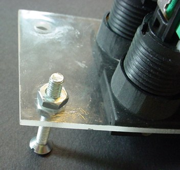
I found it was best to use the switch assembly with the screws bolted into it and adjusted for proper locating and fit to the torso for first gluing them in place. Without it you would have to hold them or possibly tape them in place, not easy. I had to do several fit ups to get it right before committing to gluing them in place. I suppose everyone figures out their own method on just how to do it.
Fit in place, note my screws were a litte long, this can be a problem installing and removing the bezel depending on the size of your clearance holes.
I used washers and wingnuts to hold in place.
I did a test fit of the buttons. Lay the torso down on the front (on the carpet) and correctly lay in the switches. Then the switch assembly bolted in place. Testing them out I could then determine how much space was between the buttons and the switches.
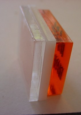
I found that when mounting the switches in the torso I had to add another piece of plastic to the back of the buttons to fill the gap between them and the switches. I added a 1/8 inch thick piece of clear plastic to all of them and then retest fitted them. Note the button fronts are not glued to the switches.
I found for the 6 center buttons I had to add another piece of about 1/16 clear plastic to them. When adding the second thinner piece I use double sticky clear tape instead of glue just to be sure it was the right thickness, but will probably just leave it. Seemed to work fine. Depending on your torso the thickness required may vary. I just did several test fits.
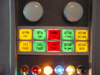
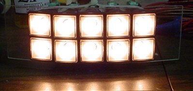
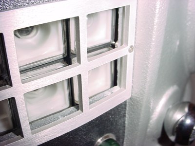
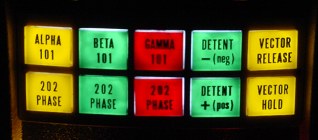
A test lightup with the LEDs
Hard to photograph to get the actual way they look. Some white light seepage around the buttons and the bezel. I may or may not remove the buttons to blacken out the edges of the diffuser to eliminate this.
I used a black Sharpie to color the edges black to help keep light from showing through to next switch. Let it dry a day or more so it cures and do a second coat. Or you could paint the edges with opaque paint, doesn't have to be black.
I did the same with a Sharpie to the edges of the clear fronts of the switches.
Wiring and Control Assembly
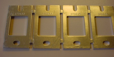
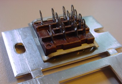
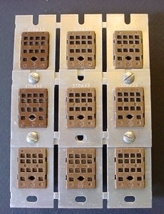
I found some original mounting strips for the relay sockets on the internet. These were new old stock and a lot less expensive than new ones. A lot easier than making a mounting plate with square holes in it. Although a custom plate could save some space.
This is how the sockets fit into the brackets. There is a hard to find retainer clip, and when you do find them they are expensive so I decided to just epoxy these into place.
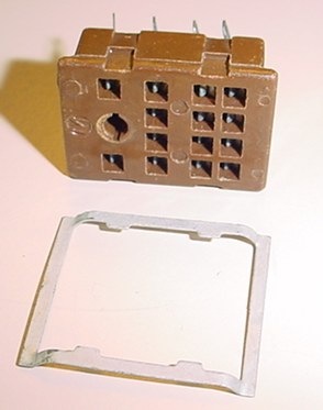
This is the retainer clip, I happened to have 2 of them in a parts box.
But I'll use them on another part of the project.
This is how the clip would fit, and would be pressed down into the slots on the side of the socket.
Once installed they can't be removed without breaking the clip.
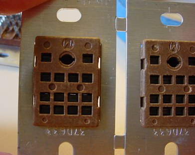
To epoxy the sockets in place you can see there are the 4 notches on the sides of the socket.
These have to be covered to prevent epoxy coming through the front.
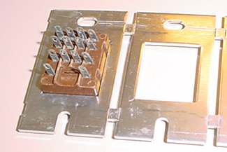
I am mounting them in 3 strips of 3.
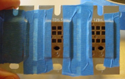
Taped off the fronts to prevent glue from coming through.
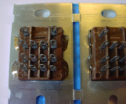
I used 4 spots of epoxy, 2 on each side of the socket to seal into the notches on the socket.
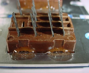
Epoxied in place.
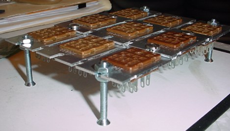
This is the assembly of the relay sockets. Overall 4" by 5-3/4"
Using old technology takes up a lot of space. Almost wish I chosen another route on these.
I may mount the relay bank inside on one of the walls of the torso, possibly with the screws shown here epoxied and puttied to the torso. Or I may make two brackets one for each end and mount them to the torso. Haven't decided yet.
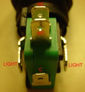
Detail of the connections on the switches.
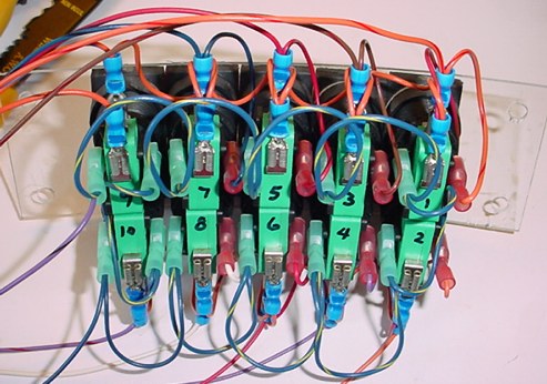
In process of wiring the chest switches. I had to leave enough wire loop between them so an individual switch & bulb assembly can be removed for bulb replacement.
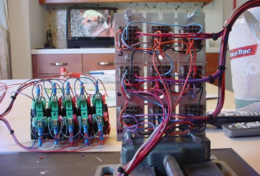
Wiring the completed switch assembly to the relay bank sockets.
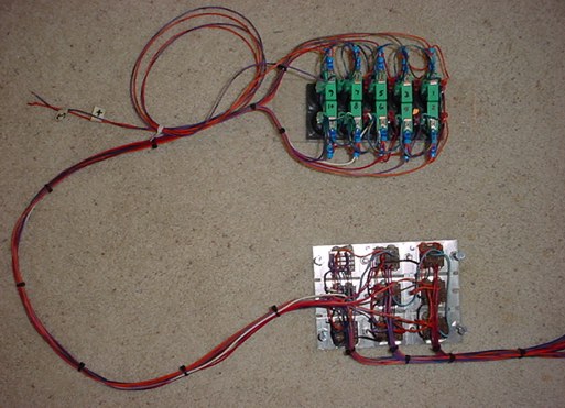
Completed wiring assembly of the chest swiches and relay sockets. Teh two wires toward the upper left of the picture are the power connection for 12vdc that powers the whole switch assembly. Simple wire ties keep the whole thing fairly neat.
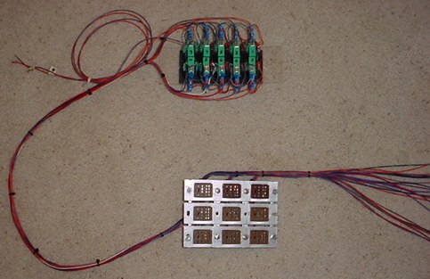
Same picture just with relay sockets turned over. The wires going to the right of the picture are the relay contact control wires that will be used to switch on various functions of the robot. (I may terminate these wires to terminal strips to keep things neat and orderly and to allow for easy connection into various circuits in the robot.)
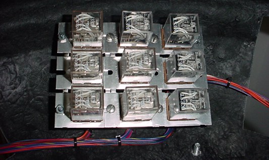
Picture of the relays installed in the socket assembly.
More to Come