Bob's Lost In Space B9 Robot Project | home
Misc. Parts | Motor Shaft Extensions | Knees & Hinges | Treadsections | Tread Making | TreadMaking from Tires | Drive Parts | Drive & Tread Installation | Tread movie | Barry's Tread Movies | Drive Upgrade | Legs | Donut & Waist plate | First Stackup | Torso | Neon | Arms | Microphone & Knob | Chest Buttons | Power Pack | Torso Vents Misc | Making Vents | Large Vent Drawings | Arm Mechanism #1 | B9 Arm Mech Dev. | Wrists & Claws | Collar | Radar | Motorizing Ears | Making Sensors | Brain | Brain Cup & Light Rods | Bulbs & Wiring Diagrams | My Old Robots | B9 Builder's & Info Sites | Related Links | Building Reference Info | Parts Drawing Links | Site Revisions | Final Leg Assembly | Leg & Hip Assembly | Leg-Hip Action | Non-B9 Projects | 2008 TX BUILD-OFF | 2008 TX BUILD-OFF PAGE 2 | RoboCon 2009
Treadsection Drive Parts
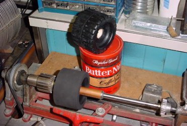
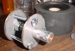
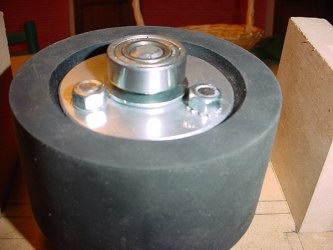
I made solid rubber drive wheels, the one on top of the coffee can is the "before" and is what I bought for about $3 at NH Northern in the trailer section. They were in with the boat trailer rollers, I have no idea what they're really for. The one in the lathe is after I have turned it down by cutting off the left and right edges with a hacksaw blade and using a large coarse file to take the tread off the wheel. They come out to be 2" wide and 3-7/8" in diameter.
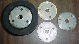
Next I had to make hubs for them. I bought 1/8" x 3" wide steel at the hardware store and cut the four circles. I roughed them out on my metal saw and ground the edges smooth. Not easy.
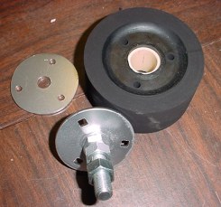
Since I'm using carriage bolts, I filed out the holes to square to fit the bolt heads. Also I placed this in position on the wheel to keep it centered and using it as a template drilled the 3 holes through the rubber wheel. Since my dimensioning is not exact, I also put registration file marks on both hub pieces and the wheel so I always put it all together the same way.
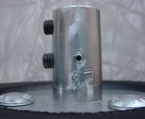
Using the motor arbors this is how it fits together.
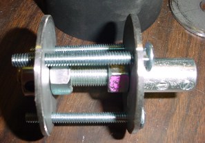
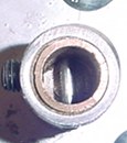
The nuts just fit on the inside of the molded in bushing in the center of the rubber wheel keeping it centered. I later did weld the motor arbor to the steel disk on this drive side. Nuts and lockwashers were not enough to prevent it from working loose under repeated reversal torqued startups.
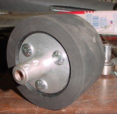
Assembled.
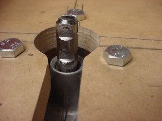
Next I had to file flats on the shaft for the set screws and replaced the set screws that came with the arbor with hardened steel allen screws.
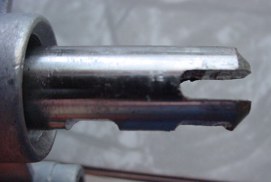
Side view of the flats.

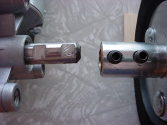
Next I drilled a hole for a roll pin in the motor arbor. This fits into the slot on the end of the motor shaft to keep the shaft from slipping and working the set screws loose. These must remain securely fixed to the motor shaft.
Roll pin installed. Also note again that I replaced the set screws that came with the arbor with hardened steel allen screws.
You can see the roll pin in place that will slip into the slot of the motor shaft.

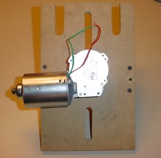
The motor mounting panel is made of 1/2" thick MDF.
The left and right outer bearing supports are made from 3/4" MDF.
Outer bearing supports located and positioned with drywall screws. Be sure to use pilot holes to prevent cracking the MDF.
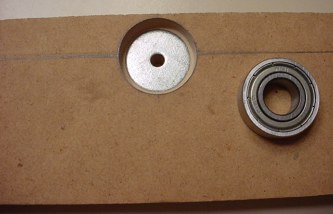
Outer bearing mount, countersunk hole for bearing to fit.
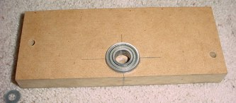
The outer bearing mount. Note the two 1/4" holes are drilled all the way through this piece and the supports and 1/2" motor mounting plate (I clamp them together first and drill all the way through the 3 pieces to keep everything aligned). The one hole is off set from center so the bolt misses the motor when assembled. They are through bolted with long bolts to secure the assembly solid.
Motor mounting.

See the next picture for why I cut the mounting adjustment slot all the way to the center hole.
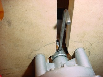
You need it to get the allen wrench in to tighten the set screw.
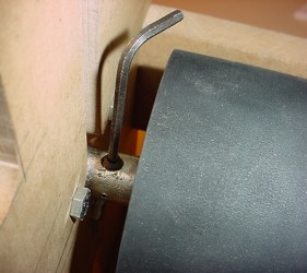
It clears on this side. This is test fitting everything together. You do need to tighten these with pliers.

On the outer end I used a large washer and one of the .125 arbor shims to space out to the bearing. Also note that I used lock washers with the nuts on the hub assembly and ground the ends of the bolts down to the nuts. This is a tight clearance assembly.
Bearing in place.
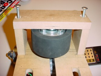
Here is how the outer bearing mount attaches with the bolts all the way through.
Click on this link to go to the next page on Drive & Tread Installation to see how it all goes together.