Bob's Lost In Space B9 Robot Project | home
Misc. Parts | Motor Shaft Extensions | Knees & Hinges | Treadsections | Tread Making | TreadMaking from Tires | Drive Parts | Drive & Tread Installation | Tread movie | Barry's Tread Movies | Drive Upgrade | Legs | Donut & Waist plate | First Stackup | Torso | Neon | Arms | Microphone & Knob | Chest Buttons | Power Pack | Torso Vents Misc | Making Vents | Large Vent Drawings | Arm Mechanism #1 | B9 Arm Mech Dev. | Wrists & Claws | Collar | Radar | Motorizing Ears | Making Sensors | Brain | Brain Cup & Light Rods | Bulbs & Wiring Diagrams | My Old Robots | B9 Builder's & Info Sites | Related Links | Building Reference Info | Parts Drawing Links | Site Revisions | Final Leg Assembly | Leg & Hip Assembly | Leg-Hip Action | Non-B9 Projects | 2008 TX BUILD-OFF | 2008 TX BUILD-OFF PAGE 2 | RoboCon 2009
Drive Upgrade:
Wheel chair motors, higher rpm, more torque & toothed drive wheels.
Although the friction drive has gotten him mobile at a low component cost, drive pulley slippage is still an issue and the treads tend to stretch over time because of the tension and therefore need retensioning periodically. I am also using very inexpensive batteries. This is why I am going to upgrade to a higher power no slip system that does not rely on tension and friction to drive the tread belts. It will be fairly costly due mainly to the cost of the motors and proper batteries. I will also be making new treads with proper more accurate spacing to fit and work with these drive wheels, see bottom of this page.
Since I don't know a machinist locally, don't have a metal lathe or mill and I am too cheap to pay a machine shop for this, I will be taking a sort of long way around on making these drive wheels and motor shaft extensions/hubs. I will use files, emery paper and my metal bandsaw to do most of the work. Total cost for both drive wheels will be very low. I will give up some extreme precision that a machine shop could provide, but I think I can come close enough by hand to make it all work.
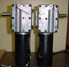
These are the new drive motors. They are wheel chair motors with gearbox, left and right. I will not have to worry about having enough power with these. These are new surplus motors built to metric dimensions. Below is some spec info on my motors and #2 below NPC is the only source that I am currently aware of for motors like these:
100 RPM INVACARE, #107569.
The manufacturer is HUAFENG ELECTRICAL in China.
Ball bearings throughout. Two styles of these motors: left & right.
Permanent magnet, reversible, rated for operation on 24 VDC.
The no-load speed is approx 110 rpm with a no-load current of approx 3.6 amps.
The rpm is about 100 rpm with a load of 60 in-lb @ 7.9 amps.
Max rated torque is 120 in-lb with an output 94 rpm @ 13.2 amps.
Gear ratio of 32:1.
These motors have a 24VDC electrically operated friction brake mounted on the rear of the motor. The braking torque is rated at 200 lb-in at the output shaft. The brake coil can be connected directly across the motor input terminals so that it will release when the motor is operating and brake the motor when the power is deactivated. Optionally, the brake can be removed from the rear of the motor by removal of two screws.
Shaft: 17mm dia x 1-3/4" long. The shaft has a 6mm wide straight key slot and key. The key runs almost the full shaft length.
The end of the motor shaft is tapped for an 8mm x 1.25mm pitch screw.
The motor was designed to be mounted by clamping the gearbox body onto the tubular frame of the wheelchair. The body of the gearbox has a half round recess and three tapped holes. The recess appears to fit an approx 1" dia tube or other circular member. Clamps not available. The tapped holes are for 6mm x 1.0mm pitch screws and extend into the interior of the gearbox and should be plugged if not used to prevent entry of dirt or moisture.
Output shaft is provided with a spring loaded sliding final reduction spur gear that can be slid out of mesh with the mating internal gear via a small lever located on the face of the gearbox. This feature allows the output shaft to freewheel. Dimensions: 4-1//4" wide (excluding shaft) x 5-3/8" high x 12" long.
|
2. NEW motors with inches dimensions (and 3/4" shaft) are from NPC Robotics and are brand new and they are $436 each: http://www.npcrobotics.com/
They also have nice hubs made to fit them that you can buy extra, that could be used to attach to a drive sprocket.
|
I will be looking for another source for heavy duty motors as time goes on as I do have a second robot planned. Although that may end up a different type of motor as these are becoming cost prohibitive for your average home bot builder.
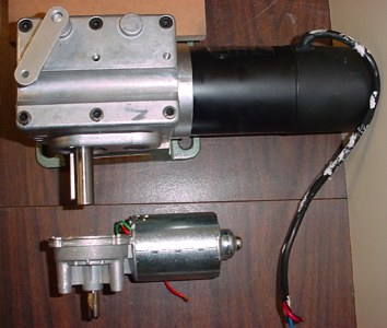
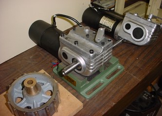
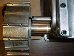
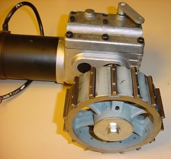
Just to give you an idea, here is a comparison of the original Dewert Motors I used and the new Wheel Chair Motors. There is NO comparison!!!
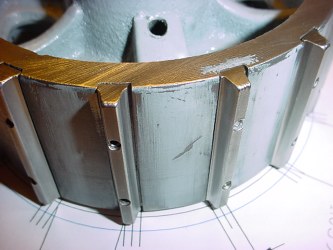
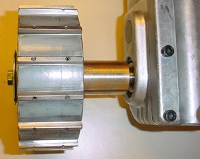
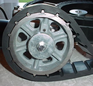
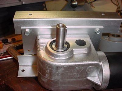
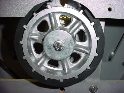
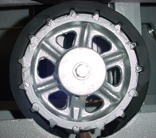
This gives a little perspective on the size of the motors, the drive wheel is 5" in diameter.
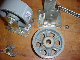
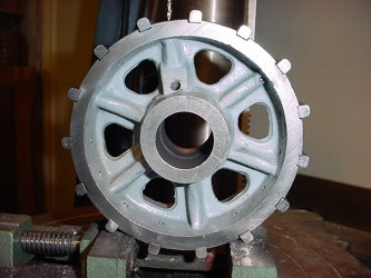
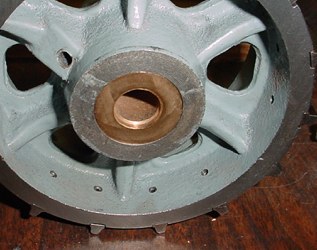
This is what I am making my new prototype toothed drive wheels from.
These are flat surface cast iron 5" dia. x 2" wide castors that cost $5.99 each at NH Northern. I dismantled them and removed the roller bearings.
Next I made a layout for evenly spacing the teeth, to work out with the diameter of wheel and the tread spacing and groove size I will be using on my new treads. I am slightly modifying the tread block spacing to work with this diameter wheel since I don't have a machine shop and need to start with an off the shelf item.
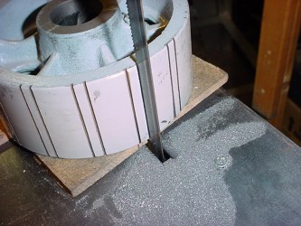
After laying out guidelines, I used my metal cutting bandsaw to cut the slots where the teeth will be added.
I used several saw cuts to remove most of the material between my guidelines.
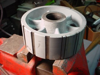
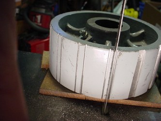
After cutting the slots, I smoothed the bottom of each of them with a square file.

To make the teeth, I started with 1/4" square steel stock from Home Depot. 36" lengths are just a couple bucks each. I cut them into 2" long pieces.
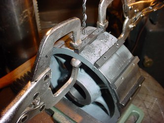
Next I attached them by clamping to the wheel and drilling 1/8" holes through both the tooth and wheel at the same time to maintain alignment for roll pins
The roll pins I acquired from McMaster Carr, again very inexpensive that way, $2.75 for pack of 100. I used 1/8" dia x 1/2" long 420SS (Stainless steel) Spring Pins, McMaster Carr #92383A252. You simply drive them into the holes with a hammer. They are actually slightly larger than the 1/8 hole so they drive in and hold very tightly.
Here is the wheel with all the teeth mounted. I have started to shape the teeth.
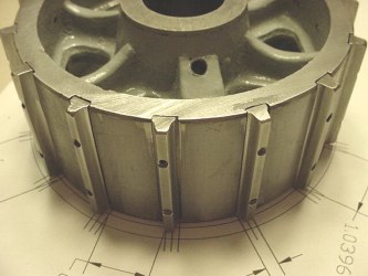
Final shaping of the teeth done on my 1" emery belt sander, by hand and "by eye".
After working out the method on this first prototype, the second one will go a lot faster, and should come out even better.
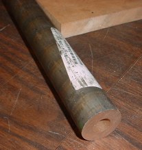
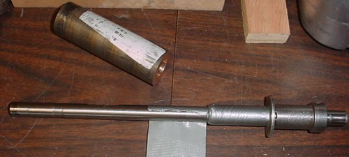
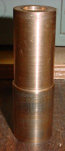
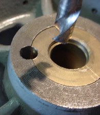
I will be making hubs for these wheels from Bronze cored rod 1-1/4" O.D. x 5/8" I.D. McMaster Carr #8911K23. Since I don't have a metal lathe, I will drill it out to 17mm for my motor shaft using the core hole as a pilot hole guide. I also purchased a 17mm drill bit from McMaster Carr.
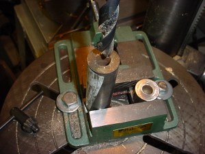
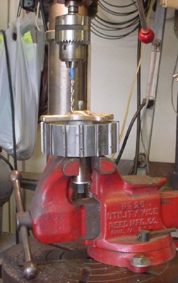
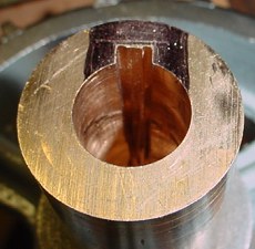
First I cut two pieces to the length I needed in my case that is 4-1/16". I had to enlarge the bore to fit the motor shaft which is 17mm diameter. It is only necessary to drill deep enough for the length of the motor shaft. It is very critical to solidly clamp everything in place and bolt the vise down to the drill press table. If the vise is not clamped down the bit will bite and pull too deeply into the piece and lock up in it. You cannot do this with a hand drill, it will also bite into the piece as you cannot control the feed properly. Proper "V" shaped jaws in the vise would make holding the round piece much easier and safer than the way I did it here.
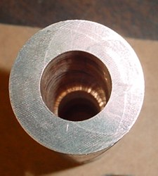
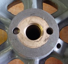
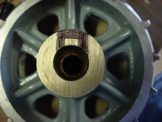
Here is the finished 17mm counter bore to fit the motor shaft.
Here is how I set up to hold it in my small old wood lathe. I used a 1/2" diameter shaft with a couple of locking collars on it. I placed a large washer over the shaft next to the collar. Then I got out the duct tape and wound enough on the shaft to fit tightly into the bore on the hub.
After slipping the bronze hub stock snugly over the duct tape I slipped on a thick rubber washer and the second locking hub. I tightened the collar set screws while using pressure against the collar to lock the hub stock tightly in position.
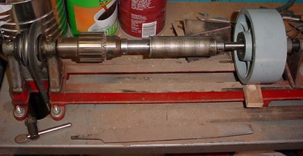
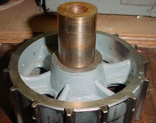
Here it is chucked into the lathe. I slipped the drive wheel over the shaft so I could check my progress with the emery paper as I work on it.
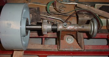
I added a 1/2" bore pulley to the tail stock to provide a sleeve bearing socket to support the the end of the 1/2" shaft. A little axle grease in the center before slipping the shaft into it will keep it lubricated.
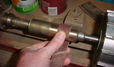
I am using emery paper to reduce the hub diameter to fit the drive wheel by emery papering it down to the proper diameter. I only reduced the diameter of the portion that needs to fit into the drive wheel about 2-3/16" wide section. I used a file to get the shoulder marked and started at the right place.
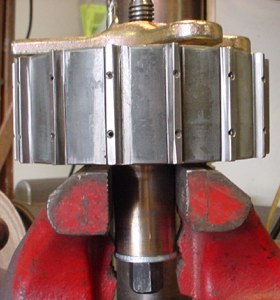
This will give you an idea of how much I had to take off to fit the drive wheel. I just kept fine tuning it until it fit the wheel.
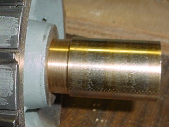
Nice fit.
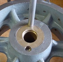
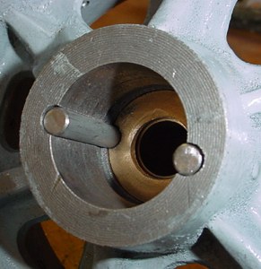
Here is my drill press setup to drill two 1/4" diameter keyways to lock the hub to the wheel.
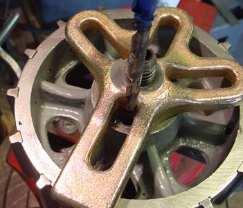
I had to be creative to clamp this assembly together with whatever I could find in the shop. I used a steering wheel puller to clamp the hub to the wheel and then clamped the hub into the vise which is bolted down to the drill press table. I adjusted the position of the drill press table and the vise to allow drilling 1/4" diameter holes, approximately half through the hub and half through the wheel. See below.
I rotated and repositioned the clamp to drill the second hole/keyway.
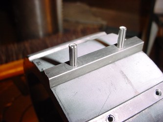
I cut 2 pieces of 1/4" diameter steel rod for the locking pins/keys.
Here you can see the keyway in both pieces.
Here is another view of both pins/keys.
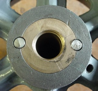
The hub will never slip in the wheel now. To hold this together I am using a long bolt through a large washer which covers the two pins and hub and holds them in place by threading into a hole in the center of the motor shaft. With the dual bearings in the motor gearbox, I should not need an outer bearing at this side of the drive wheel. This is a very sturdy assembly on a 17mm motor shaft. The wheelchair motors were designed to have the wheelchair real wheel hubs bolted directly to the shaft and take the weight of the chair and occupant.
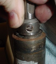
The motor shaft has a key which I will utilize by cutting a matching keyway in the hub to lock them together.
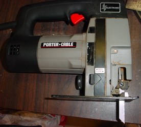
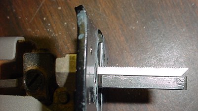
I used my jigsaw to rough cut a keyway for the motor shaft key. You need a saw with blade guides for best results with this method. This saw has a roller guide behind the blade and side to side guides. It helps make a straight vertical cut.
I chose a metal cutting blade and adjusted it for the full depth of the key at the full downstroke of the saw blade. In the pic above I laid the key that came with the motor shaft on the blade to show this.
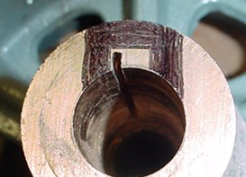
I marked the section to cut out for the key size.
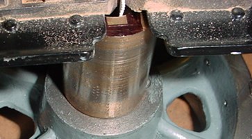
Positioning saw to make first cut. Set the saw to a medium to slow speed. Keep the saw perfectly vertical and cut slow for the first left and right side cuts to assure they are as vertical as possible.
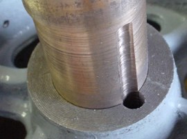
Results of first cut.
Results after several cuts to take away the material. I purposely stayed inside the lines so I could use a square file to finish it out by putting it back in the vise and hand filing to fit the key. That is not quite as easy as it sounds. The saw blade tip does not cut exactly the same as the top of the blade at the blade guides. The blade tip tends not to cut as deeply no matter how careful you are. So more filing is required the deeper into the hub keyway you go. The filing took some time.
After all of this to make the hubs, if you have a machinist friend do ask him to make the hubs for you and do all the keyways. My method is crude at best, it works, but is a lot of work to do. Not at all how these are really cut. A machinist would broach it, of course he would have the equipment & tooling to do it.

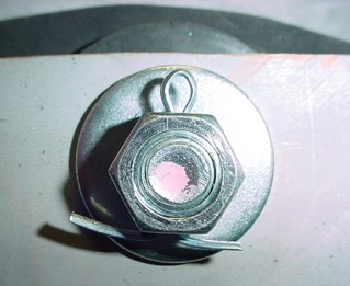
Here is the bolt that threads into the motor shaft to lock everything together. The large washer holds the wheel keys/pins and wheel in place. With this method no set screws are necessary.
A couple views of the finished assembly, except for painting the drive wheel.
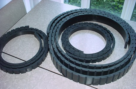
Here is all the new tread material I cut grooves in spaced to fit the teeth on my drive wheel. I need to take apart my treadsections and line everything up and test fit the treads to determine the final length I will need before I cut and seam them together.
I wrapped the tread around the drive wheel to show how the teeth engage into the tread. I made these for a little play, there will be some stretch due to the load on the treads, I do not plan on using much tension, just an idler wheel or roller to take up slack in the top of the tread bays. That will be between the top two treadsection wheels.
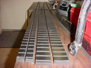
More treads I made for another drive system in development.
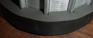
Tread fit to drive wheel.
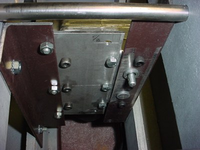
I had to make brackets to attach to the motors and to the inside of my treadsections. This is a pic of the mounting parts before painting. The burgandy angles are pieces cut from an angle iron bed frame.
Motor mounting plate, cut from 3" wide 1/8 " thick steel plate. I measured and transferred all of the required hole locations from the motor to the plate. Note the arm on the motor is a mechanical engage-disengage lever for the final gear. Disengaged the robot would be able to be rolled freely.
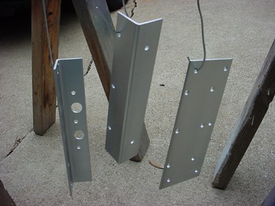
Here are the angles and mounting plates getting a shot of paint before assembly.
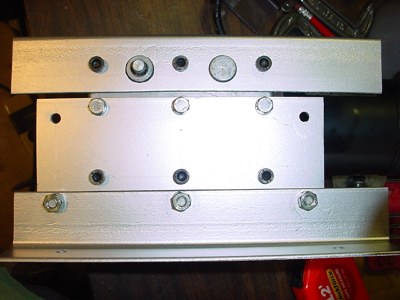
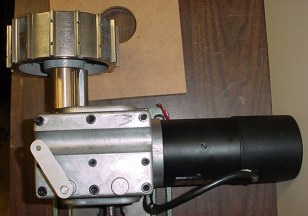
All the pieces mounted to the motor. And all this has to be done twice! Left and right sides!
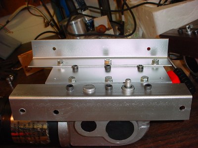
The backside.
Putting it all together:
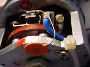
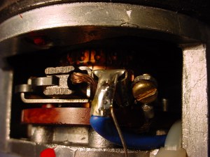
First off it is important to put RFI prevention capacitors across the brushes in the drive motors. It is recommended to put a .001 to .01 mfd disc ceramic capacitor across the brushes and also between each brush and the motor frame. This will prevent problems with the radio control receiver. Tip from the battlebot experts. I've found it helpful to obtain some of the various books written on the battle robots and they have tons of great info and tips.
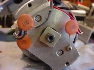
My motors are large and so this was fairly easy. Also I removed the mechanical brakes from the motors so you can see that I used the tapped holes to secure one end of the capacitors to the motor frame. It is a lot easier to do this now because it is somewhat time consuming to remove the motors once they're installed. These motors have a cover that goes over the back end so the caps and connections are protected.
I set the treadsections on the bench upside down so I had a nice working height. You can see the I've preinstalled all the treads.
I installed the idlers in the upper section. Notice I had to grind down the bolt head to fit within the depth of the treadsection side panels.
Here is a view of the tread over it. These treads stretch since they're made of just solid rubber and also this keeps the treads from hitting the inside top of my treadsection assembly due to the 1/2" thick added pieces I added for strength of the side gable assemblies.
Here is a backside view of the nut. I drilled a hole through the nut and bolt to secure it with a cotter pin. Since the idler is just spaced by washers and does not have ball bearings I couldn't just crank these down tight.
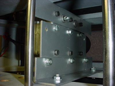
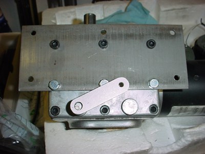
After snaking the motor and bracket assembly in through the side opening of the treadsection, it was bolted in place. You can see the upper and lower bolts on one bracket in this picture. And yes, I had to test fit this several times to properly locate the holes and drill them.
Here is the other side bracket, you can see the top bolt and where I had to redrill it to lower it (lower left corner of this pic) because I mis-calculated the location originally and it was going to hit an inner tread wheel.
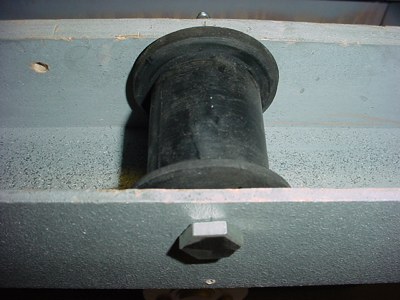
First you can see that I had to trim out a section to allow the sprocket to slip straight onto the drive shaft.
Without doing that it is too difficult to work on it or assemble it.
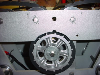
After bolting in the drive motor assemblies, I slipped the sprocket into the belt over the drive shaft and bolted it down. I did temporarily take out one of the wheels to allow some belt slack to do this.
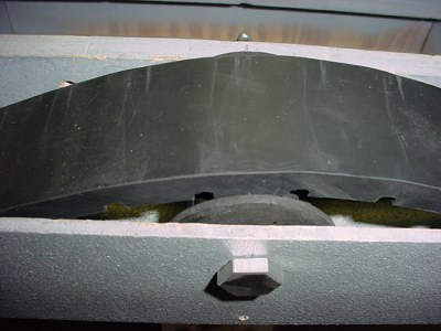
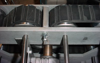
Here you can see the tread path I am taking with these. One reason is to take up slack as the treads stretch and during turning this helps to keep them on the drive wheel. A little less tread on the ground also helps reduce some of the friction, but the main reason is for keeping a tight grip around the drive sprocket.
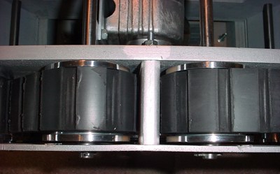
You may be wondering what this divider piece is between the belt going up up and over the drive sprocket. This is another solution to the tread stretching problem. During turns which create high torque on the belts the belt stretches where the loop is coming off the sprocket and running back down to the ground. When this happens it can actually hit the other section of the belt and the grooves will lock on each other stopping the drive. Interesting to see, but really hard on the belts. Combination of this divider with at least one side of the belt looped over the next wheel helps stop some of this.
You will notice some wear on the treads, I've been doing a lot of testing. Driving your robot by the treads is very hard on them. Partly due to the tread design, it was never made to work with square groves. The edges of the belt groves need to be tapered (like a timing belt) to properly engage on any sprocket. I knew this going in, but seeing what happens is a lot of the fun. And the wear is partly because the glossy surface will wear off. Rubber on concrete! Tank steering rubber on concrete, and you loose bits of material.
Here is the opposite side sprocket. I decided to weld the teeth on this one rather that pin them. Not as pretty but works too. Any way you try to make a sprocket from scratch is not necessarily easy. Especially if you really don't have a metal shop. Again somewhat of the challenge vs the dollars it would cost to shop them out.
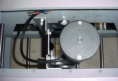
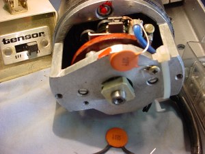
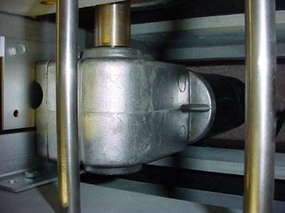
Another view of the installed motor from the top with the end cap over the brush end of the motor.
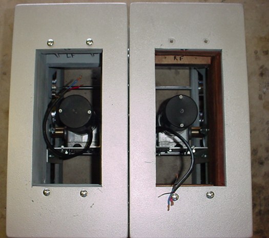
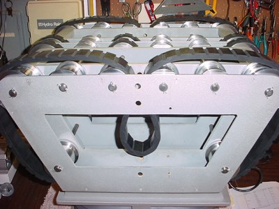
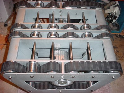
A view of both motors installed. These treadsections are a real tank at 24volts. I need to get the motor controller so I can properly test them under good acceleration control. They weigh 135 pounds currently, that's without batteries, or other accessories.
I am removing the knee plates and wooden knees as the knees and legs are getting upgraded to rubber. Plus I'll be installing a support system for the rubber knees and legs.
Go to Legs
More to come