Bob's Lost In Space B9 Robot Project | home
Misc. Parts | Motor Shaft Extensions | Knees & Hinges | Treadsections | Tread Making | TreadMaking from Tires | Drive Parts | Drive & Tread Installation | Tread movie | Barry's Tread Movies | Drive Upgrade | Legs | Donut & Waist plate | First Stackup | Torso | Neon | Arms | Microphone & Knob | Chest Buttons | Power Pack | Torso Vents Misc | Making Vents | Large Vent Drawings | Arm Mechanism #1 | B9 Arm Mech Dev. | Wrists & Claws | Collar | Radar | Motorizing Ears | Making Sensors | Brain | Brain Cup & Light Rods | Bulbs & Wiring Diagrams | My Old Robots | B9 Builder's & Info Sites | Related Links | Building Reference Info | Parts Drawing Links | Site Revisions | Final Leg Assembly | Leg & Hip Assembly | Leg-Hip Action | Non-B9 Projects | 2008 TX BUILD-OFF | 2008 TX BUILD-OFF PAGE 2 | RoboCon 2009
Knees & Hinges
The Knees were made from Mark Thompson's Bermuda Triangle plans.
The Hinges were made from Dave Painter's Benign Design robot plans (available through the club).
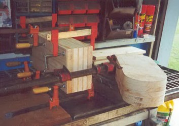
I first had to glue up 3/4" & 1/4 inch boards to make the 1" thick pieces for each knee section. To save time I glued and stacked them 5 sections at once.
Then I cut the rounded ends on my bandsaw. I then stacked them and sanded them all even on my disc sander.
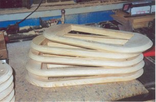
The next steps were to route the edges at a 45 degree angle on each piece and then to cut the centers out. This creates a huge mess. Since I used soft pine that wasn't completely dry and had fairly course grain, the routing didn't come out as smooth as I had hoped for. To correct that I set the table on my disc sander to 45 degrees and sanded all the edges smooth. More dust.
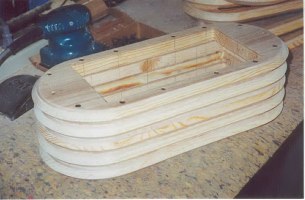
Stacked them together, center 3 sections first, pilot drilled and countersunk holes for 2-1/2" drywall screws. If you don't pre-drill you'll be in for a surprise and probably split your sections. Luckily I knew this before I started. If you look closely you can see the lines on the inside indicating where I put screws. That way when I screwed on the top and bottom sections, I didn't hit the screws in the center 3 sections. I used 1-5/8 drywall screws to install the top and bottom sections.
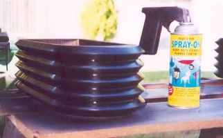
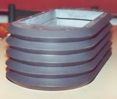
Sprayed them with Plasti-dip spray,
It's a rubber like coating. Then painted them with the Duplicolor Vinyl & Fabric VS11 Charcoal gray paint. Actually the Plasti-dip didn't really add much to the look. If I did them again, I'd just fill, sand, coat with sanding sealer, sand again and paint.
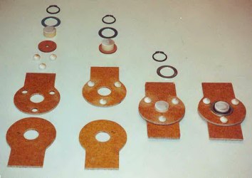
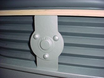
Here are my knee hinges. I made them from 1/8" masonite, a little thicker than the original ones, but you can't really tell. I used wooden hole plugs for the rivets, 1" dowel for the pin and a real washer and split retainer ring to make them look realistic. You can see they'll function, but they don't need to since they are just for aesthetics on this bot.
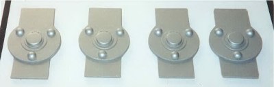
Primered and painted (same color as treadsections and torso), 1978 Alfa Romeo silver.
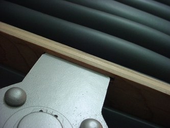
A closer view.
Note that the rivets look darker in color here, but they are not. Picture was taken with a flash almost straight on and this is the effect produced by the round heads. Makes them appear darker doesn't it? Just goes to show you that when you are looking at the TV show and photos of the robot, that some of what you think you see is just an optical illusion.
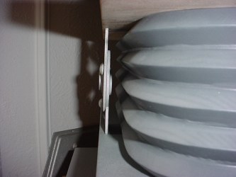
Here is a view of a hinge test fit.
I haven't yet painted and textured the knee plates.
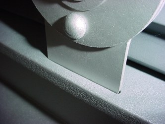
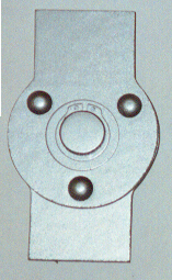
This shows the inset from the edge.
The inset from the edge of the kneeplate.
Front View.
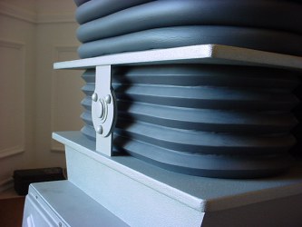
Kneeplates painted and assembled to treadsections.
I used eight 1/4-20 x 6-1/2" long carriage bolts to attach the kneeplates & knees to the treadsections.
The pieces are stacked together and hinges fitted into the precut slots.
The bolts fit through the predrilled holes and washers and nuts secure the assembly from inside the treadsection top plates.
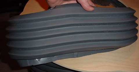
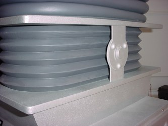
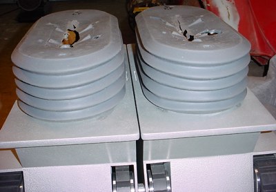
I bought a set of 'reject' rubber knees from Will Huiff, and these are great for rejects in my opinion. They were part of a total set of arms/legs/knees and bubble lifter boot all with minor defects you won't see once everything is assembled. He sold them on Ebay and I got them at a very special price. I am extremely happy with these.
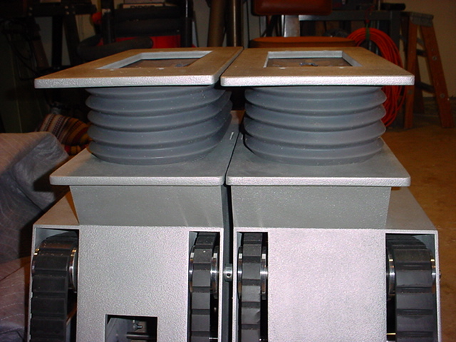
Here they are test fitted and they look very nice. If you purchase legs and knees from Will for your robot and have wood treadsections and kneeplates, you may or may not want the knees and legs attached to each other. Will offers them either way. I personally found it easier to work with them as separate pieces. Easier for robot assembly. Although you will have to provide internal support for the tops of the knees to the kneeplates if you get them separate. You can see my knee supports on my Final Leg Assembly page. For me it was much easier to be able to remove the leg section without having to also remove the knees. It somewhat depends on what you are doing with your robot. If he is mechanized, then internal access without total disassembly is advantageous.
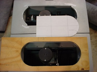
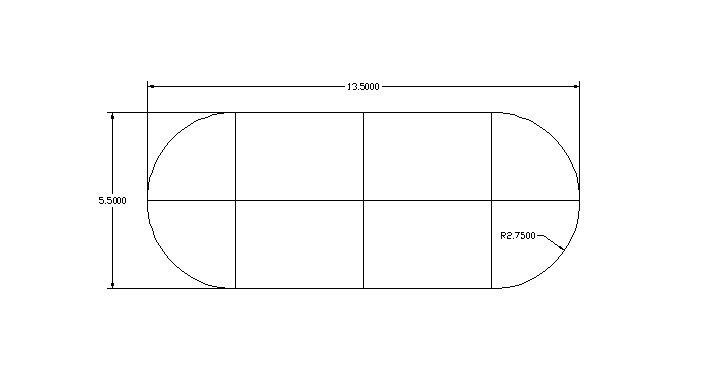
First off I made a template to test fit to the bottoms of the new rubber knees so I could trace it and alter the openings in my treadsections.
If you want this template, click on the following pdf link.
Test fit to template.
Also note that I will cut the extra rubber that protrudes above this 1/2" thick template off, so they will fit properly into the top plate of my treadsections. I marked it with a Sharpie and cut it off with scissors.
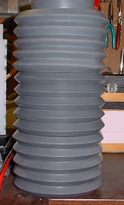
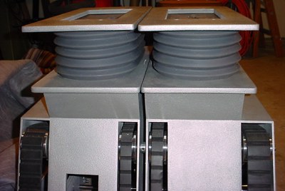
Picture just for the heck of it. The two wooden knees stacked with the rubber one on the top.
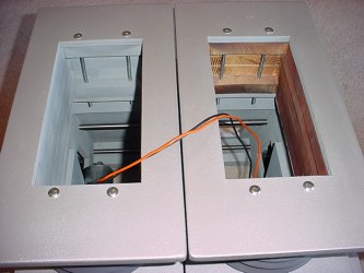
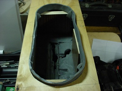
I traced the template and rounded out my rectangular holes to fit the new knee sections.
Here is the first one.
Both sitting in place. Note the top centers get trimmed out.
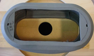
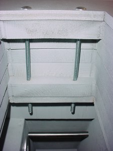
Here is the knee with the top cut out. I used my template to mark the section leaving enough edge to fit and support it with my leg supports. There will be some additonal internal supports to keep it looking nice. Note this one is marked LF (Left Front) as I typically do with everything that is 'hand fit' to assure it all goes together as planned in the end.
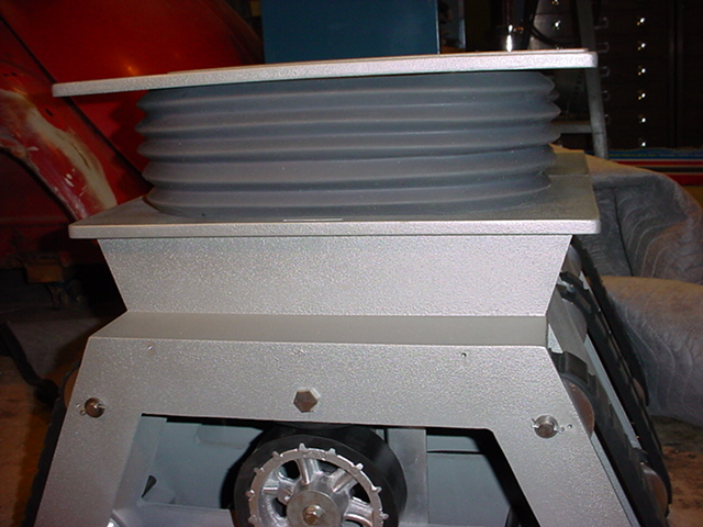
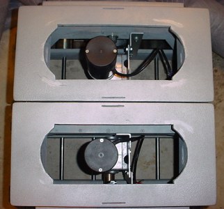
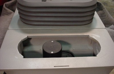
Side view
These are nice knees. In case you wondered, they are temporarily being internally supported with some blocks as they are quite flexible.
Go to Treadsections
Or
Go to Final Assembly