Bob's Lost In Space B9 Robot Project | home
Misc. Parts | Motor Shaft Extensions | Knees & Hinges | Treadsections | Tread Making | TreadMaking from Tires | Drive Parts | Drive & Tread Installation | Tread movie | Barry's Tread Movies | Drive Upgrade | Legs | Donut & Waist plate | First Stackup | Torso | Neon | Arms | Microphone & Knob | Chest Buttons | Power Pack | Torso Vents Misc | Making Vents | Large Vent Drawings | Arm Mechanism #1 | B9 Arm Mech Dev. | Wrists & Claws | Collar | Radar | Motorizing Ears | Making Sensors | Brain | Brain Cup & Light Rods | Bulbs & Wiring Diagrams | My Old Robots | B9 Builder's & Info Sites | Related Links | Building Reference Info | Parts Drawing Links | Site Revisions | Final Leg Assembly | Leg & Hip Assembly | Leg-Hip Action | Non-B9 Projects | 2008 TX BUILD-OFF | 2008 TX BUILD-OFF PAGE 2 | RoboCon 2009
Legs
The Legs were made from Mark Thompson's Bermuda Triangle plans.
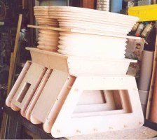
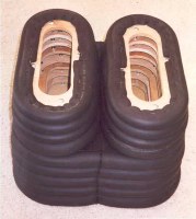
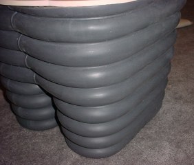
This is the only pic I have of the leg frame pieces before they were wrapped with insulation. Just stacked on top of the knee plates.
This is 3/4" Armaflex foam pipe insulation, available at Home depot. It comes in six foot lengths. I bought the inexpensive uncut kind and cut it lengthwise with a single edge razor blade. (Get several blades-as the insulation dulls them after just a few.)
When wrapping each of the plywood frames with pipe insulation, I first just stapled the insulation to each section of plywood and used a million staples. This was easy, looked good in pieces but when I stacked them up, they were only 10 inches high. Guess I stretched the insulation too tight while I stapled it. It's tough to do with just staples and keep from flattening it.
I didn't like them only 10" tall so I took off all the insulation and tossed it and started rewrapping the frames with new insulation. This time I used hot melt glue on the edge of the plywood doing 6 to 12 inches at a time and just holding it in place a few seconds until it sets. This worked out pretty well and I didn't have to clamp or wrap it to hold it in place until the glue dried.
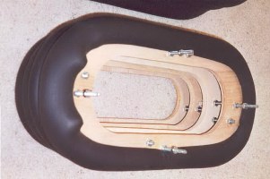
As you can see I used 1/4" dia. carriage bolts to bolt each section to the next one. I used nuts on each side of each piece to allow for vertical adjustment and to lock everything in place. The bolts were 1/4-20 x 2-1/2" long. I alternated the location of the bolts on each section using 4 per layer. This transmits the weight from top to bottom through the bolts. No special measuring needed, just position the layer properly, clamp from inside and drill the 1/4" holes by eye - it's not critical. Some builders have used long threaded rods from top to bottom for perfect alignment. I felt the carriage bolts gave me the ability to position each layer separately and I can take them apart between any 2 layers if they ever get severely damaged by removing just 4 nuts, without having to separate all layers from single threaded rods. Also I used no glue, caulk or goop between the layers, again for ability to disassemble.
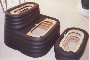
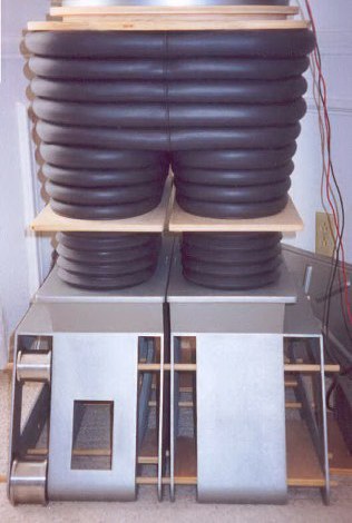
All sections bolted together.
Note the bottom two leg sections, I left the insulation stapled. They're a little flatter but on the show the lower sections always seemed more squished most of the time anyway. They are 13" tall, instead of the usual 14 to 14-1/2", but that's because I left the bottom sections more squished.
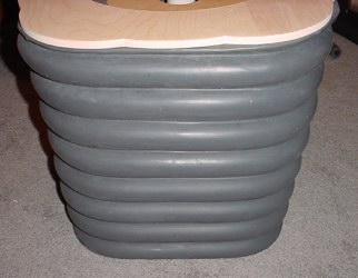
Painted
I used that Dupli-Color Vinyl & Fabric Paint, VS11 Charcoal Gray. It worked great and looks great.
I used super glue to do the seams and zipper. The only thing with super glue is that it makes the insulation and rubber kind of hard at the joint. After painting if you press it too hard you can crack the paint where the superglue was used. On the next robot I'll use GOOP instead.
Zipper was made from neoprene tubing slit down the middle.
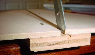
I took a scrap of wood for a base about 6 or 8" long and stapled to it two 1/4" thick scraps to it separated by the width of the tubing forming a groove for the tubing to slide through. Then I took a single edged razor blade (a new one) and pressed the bottom corner of it into the wood base so it stands up in the center of the groove (use pliers to hold it and press in the cutting edge corner, it will sit at an angle).
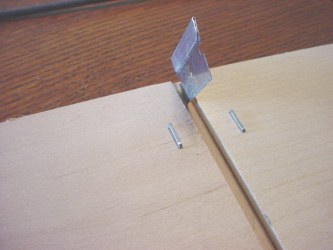
Very simple, it is a 5 minute jig.
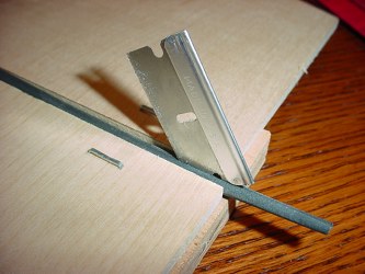
You have to start the tubing with about an inch cut with scissors or any blade so you have enough length to place it past the blade,
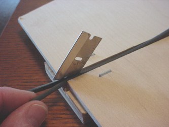
then you can pull the tubing from the backside of the blade through the groove past the blade cutting edge and you will get a nice 50/50 cut tube. Keep the tube feeding into the groove the length of the board, don't go too fast and it cuts nicely.
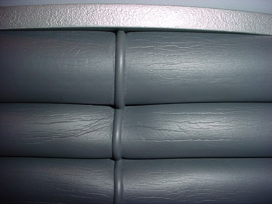
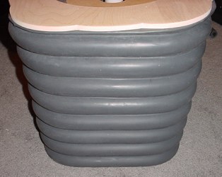
Same legs and paint job, just different camera with flash.
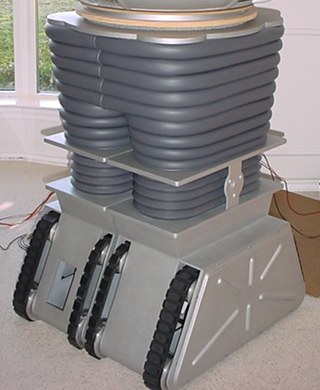
Kneeplates, hinges and side panels painted and installed.
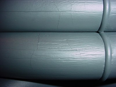
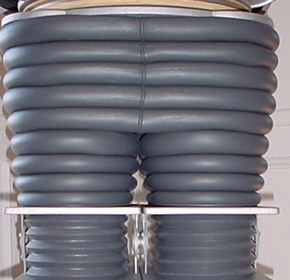
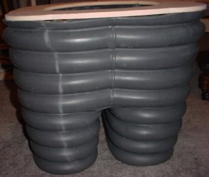
Here is a picture to show what happens with age on the legs made from the pipe insulation and painted. Originally they were very smooth and nice. You can even see some hairline vertical cracks that show up with the camera flash. I had not noticed them before. I don't think it is something preventable over time with the pipe insulation.
Here is another shot showing the horizontal compression lines. The legs still look great, but expect this to happen as they will not stay pristine and perfectly smooth over time.
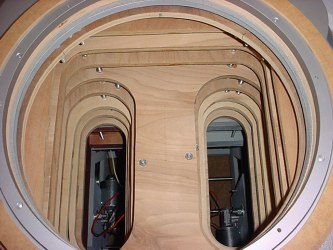
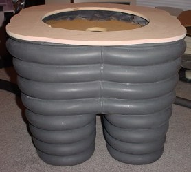
A look inside at the skeletal framework of the legs.
I have purchased a set of reject platinum cure silicone rubber legs and knees (along with the arms and lifter boot to match) from Will Huff, and I am sure you will agree these are far from rejects when you see the final assembly.
You will see here the white stripe down the back side of the left leg. That's one of the "defects". Well, I can live with that, it looks more pronounced in this picture than I think it really looks.
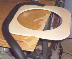
Click on the link below to go to the remade waistplate to fit these legs.
Go to Donut & Waistplate