Bob's Lost In Space B9 Robot Project | home
Misc. Parts | Motor Shaft Extensions | Knees & Hinges | Treadsections | Tread Making | TreadMaking from Tires | Drive Parts | Drive & Tread Installation | Tread movie | Barry's Tread Movies | Drive Upgrade | Legs | Donut & Waist plate | First Stackup | Torso | Neon | Arms | Microphone & Knob | Chest Buttons | Power Pack | Torso Vents Misc | Making Vents | Large Vent Drawings | Arm Mechanism #1 | B9 Arm Mech Dev. | Wrists & Claws | Collar | Radar | Motorizing Ears | Making Sensors | Brain | Brain Cup & Light Rods | Bulbs & Wiring Diagrams | My Old Robots | B9 Builder's & Info Sites | Related Links | Building Reference Info | Parts Drawing Links | Site Revisions | Final Leg Assembly | Leg & Hip Assembly | Leg-Hip Action | Non-B9 Projects | 2008 TX BUILD-OFF | 2008 TX BUILD-OFF PAGE 2 | RoboCon 2009
Drive & Tread Installation
With continuous axles all the way through both treadsections, it creates a real assembly headache to change a tread or modify anything once you have it all together. I knew this when I decided to use this design, but the strength and alignment gained from the axles has worked out well. I have been experimenting with two different sets of treads, and don't know how many times I have assembled and disassembled these in the process of fitting motor mounts, treads, drive wheels, etc.
I have not had time to get dimension drawings of my brackets, and mounting components done, but thought it would be better to wait to do that until I have finalized my drive assembly, as I may still make some changes. The tread drives are an R & D portion of the robot.
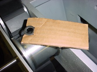
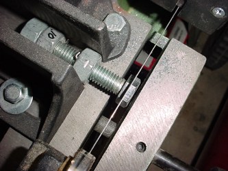
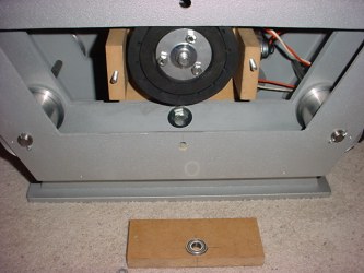
This is a special tool I made to hold the shims in place while I slide the axles through to assemble everything. You have no room for pliers or your fingers to get the shims located properly once you put the wheel in.
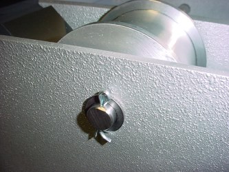
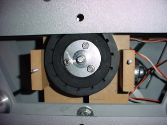
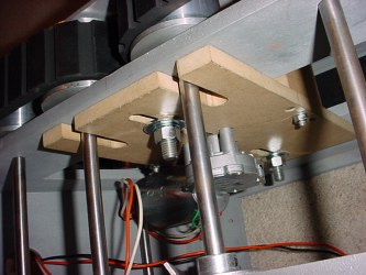
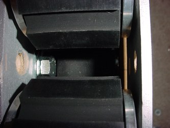
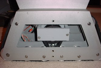
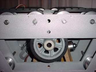
I am using an idler wheel up inside to keep my inner 1" treads off the floor to reduce drag when turning. This picture also shows the center locking collar. Its' set screw fits on a flat on the shaft.
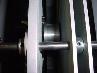
Here is how the cotter pin and .062 bushing secure the axle. I carefully measured everything to determine my axle length because you can't have these stick out too far or your side panels will not fit down over them.
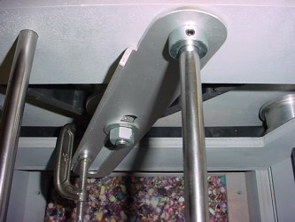
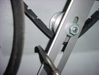
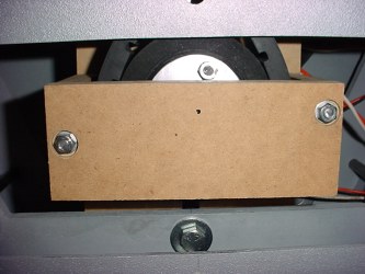
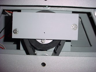
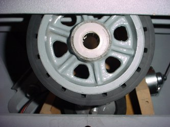
This is the mount for the inner idler wheel, the bracket mounts and pivots on the axle above. Again I used another locking collar to position it.
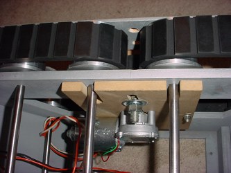
Here is a bottom view looking inside at the 1" idler wheel. You can see the right side is close to the side of the treadsection. I had to cut down the head of the bolt that mounts the idler wheel.
I cut the heads of the bolts down on my metal bandsaw to clear the inside of the treadsection for the 1" idler wheels. I suppose you could do this with a handsaw and a vise, but I prefer a power tool anytime over that.
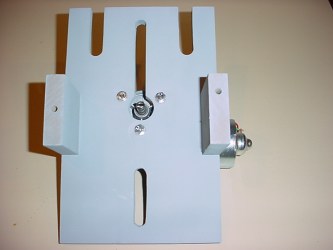
Plenty of adjustment in my bracket to allow for different length treads. The length on the 1" treads is not too critical with this setup.
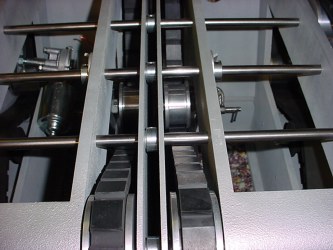
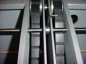
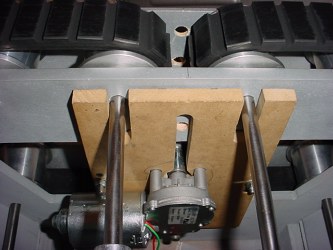
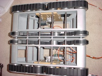
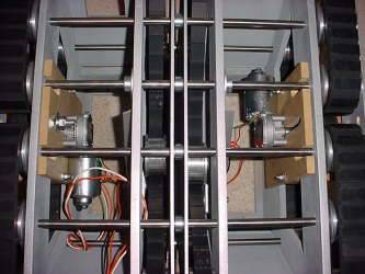
This gives you a better idea how they are installed. Note the locking collars on every axle between the two treadsections. Again check my drawings referenced on my Treadsection page for the dimensions and layout of the shims and locking collars.
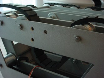
Now it gets interesting to actually install the 2" treads and the drive motors and wheels. You have to leave one wheel out so you have enough slack in the tread to fit over the drive wheel. The 2" treads you'll see in the following series of photos are Norm S. treads. The 1" treads in the previous photos are my treads.
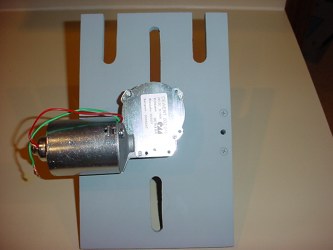
This picture makes it look easy, although the whole drive assembly will not fit into the treadsection all together. The drive wheel is installed after the motor and its' mounting plate. You can see one of the 1/2" center mounting bolts at the bottom of this photo. I use one the top and one on the bottom to adjust tension and secure the motor assembly.
Here is a better view of that mounting bolt and the outer bearing support.
Here is the outer bearing support plate installed. Don't do any tensioning until the outer support is in place.
You can see both the upper and lower adjustment/mounting bolts here. They are 1/2" diameter bolts with washers and lockwashers under the nuts on the inside.
Actually now it takes a lot of pressure to properly tension the treads to keep them from slipping on the drive wheel. This setup allows you to push down to tighten the belt and lock it down. Originally I thought that the rubber drive wheels would give better traction against the treads and prevent slipping. They do for the most part, but under tight turns or on carpet attempting to turn, the drive wheel can still slip under the heavy torque.
I have tried both my treads and Norm S. treads, shown here are Norm's. They're pretty equal in material and function. I have found that the 3/4" wide pads on Norm's provide better flexibility than the 1" wide pads on the design I used. I had to reinforce the seams in my treads with stitching and I made them a bit shorter for a V belt drive I experimented with. The V belt drive did not work anyway.
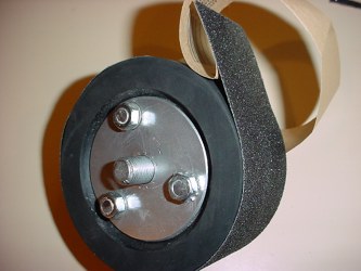
I also tried "tread tape" around the drive wheels to eliminate slipping, it worked but under heavy torque they could still slip and started to sand the surface of my treads. I removed it. You could see by the marks on the treads where I was not getting full surface area contact on my rubber drive wheels. I think a slightly softer drive wheel surface might give better gripping.
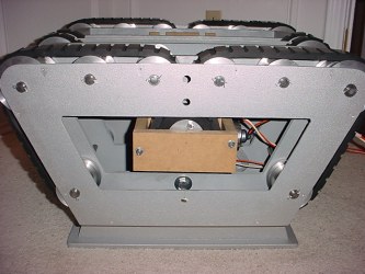
Side shot of the complete assembly.
Bottom view.
Here is the other mounting bolt head. And you can see the drive wheel below it. This is tricky to assemble.
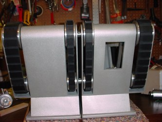
After the prototyping and experimenting, I tore it all down again to paint the parts. They look much better with a coat of gray primer on them.

The outer bearing support bracket will just touch the inside of the side panels when they are installed. The clearances using MDF are limited because of the thickness of the material needed for strength. If this was all fabricated of metal that would be somewhat less of a problem.
My two treadsections together with axles, wheels, motors, etc all assembled weigh a total of 95 pounds. This is less the side panels, soil sampler door and its' mechanism, power connector, bottom pans and whatever else I can fit in there.
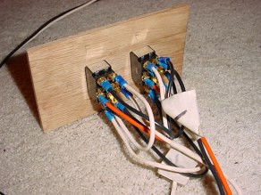
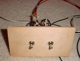
This is just my test switch assembly. It is 2 momentary DPDT center off switches that I can control forward and reverse of each motor.
The treadsection drive is testing out fairly well, I still haven't totally eliminated the occasional slipping under load. One of the problems is that the solid rubber treads require a lot of torque because of the durometer required to prevent excessive stretching.
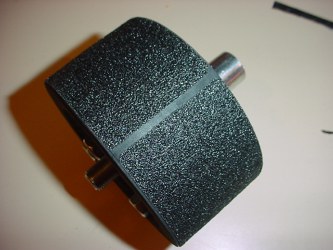
Actually larger diameter drive wheels would help some by increasing the surface area in contact with the treads. These are some I experimented with, but my current treads are not actually long enough for them.
Go to Drive Upgrade