Bob's Lost In Space B9 Robot Project | home
Misc. Parts | Motor Shaft Extensions | Knees & Hinges | Treadsections | Tread Making | TreadMaking from Tires | Drive Parts | Drive & Tread Installation | Tread movie | Barry's Tread Movies | Drive Upgrade | Legs | Donut & Waist plate | First Stackup | Torso | Neon | Arms | Microphone & Knob | Chest Buttons | Power Pack | Torso Vents Misc | Making Vents | Large Vent Drawings | Arm Mechanism #1 | B9 Arm Mech Dev. | Wrists & Claws | Collar | Radar | Motorizing Ears | Making Sensors | Brain | Brain Cup & Light Rods | Bulbs & Wiring Diagrams | My Old Robots | B9 Builder's & Info Sites | Related Links | Building Reference Info | Parts Drawing Links | Site Revisions | Final Leg Assembly | Leg & Hip Assembly | Leg-Hip Action | Non-B9 Projects | 2008 TX BUILD-OFF | 2008 TX BUILD-OFF PAGE 2 | RoboCon 2009
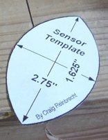
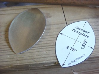
I started this process by using Craig Reinbrecht's Sensor Template.
If you don't have it you can get it here Ear Posts& Ear Sensors
or here
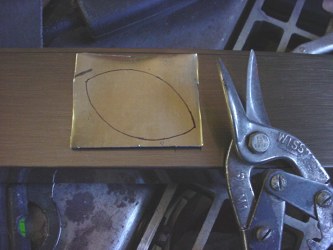
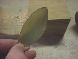
I used some brass plated steel from a fireplace surround we tore out in a remodeling project.
It is a fairly heavy thickness - 20 gauge at about 0.039"
Traced it an cut them out with tin snips.
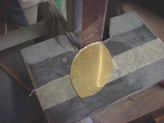
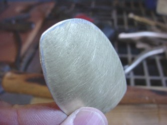
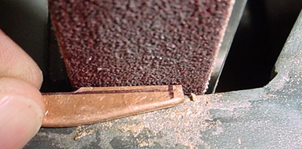
Next I cleaned up the edges with 80 grit emery belt.
I used a fine emery paper to go over the surface so the paint will have something to bite into.
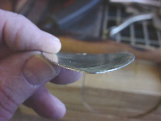
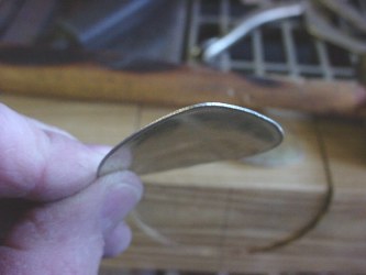
The ears have about a 2" radius curvature to them.
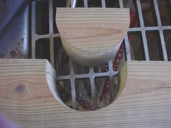
The metal I used is thick enough you can't really bend it easily or accurately by hand. To make a jig to bend them, I took a scrap of 4 x 4 and cut a 2" radius semicircle out of it. This is pressure treated 4 x 4 fir which is very dense and hard. Some woods would be too soft for this.

I lined up the sensor straight in the bottom of the jig.
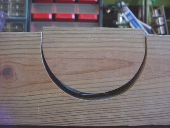
Carefully set the top in place without moving the sensor position.
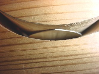
Closer look.
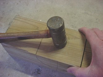
Now I gave it several good whacks with a hammer. The first one will just start to bend it. It took 5 or 6 times to get the shape. Note, here you can see the center lines I drew on the jig to line everything up.
Works very well. I won't be going into mass production anytime soon with this process!
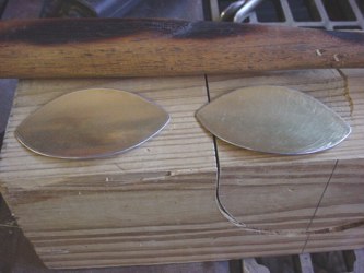
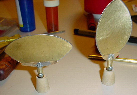
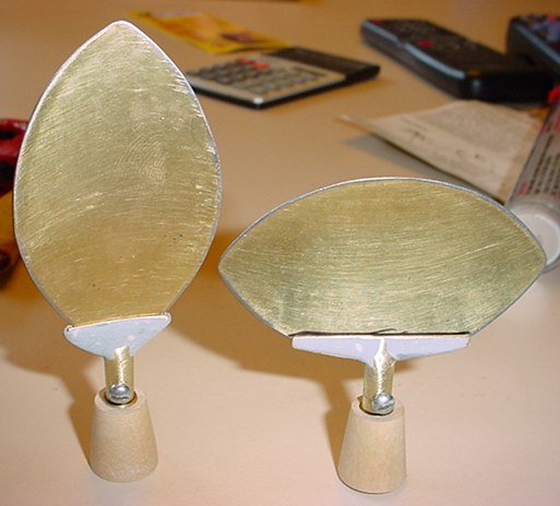
Note that both of the sensors have the same radius shape to them (from side to side) even though one is mounted vertically on the robot and the other is mounted horizontally. A common mistake is to put the radius on the horizontal one from end to end rather side to side.
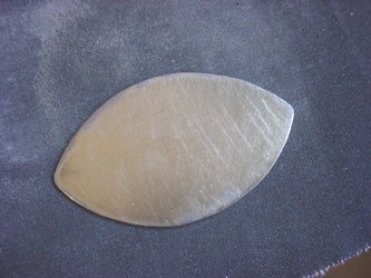
Below are some more pics of the finished pieces. Painting will have to come later when the weather warms up.
For the holders, again I started with one of Craig Reinbrecht's nicely scaled drawings.
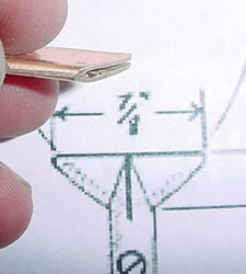
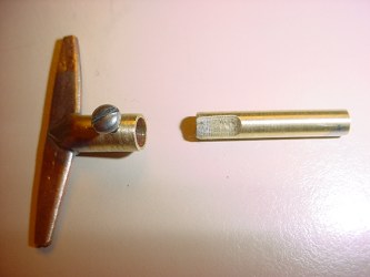
For the small holder I took a 5/8 wide piece of copper strap a little longer than 7/8", bent it in half around a scrap of sensor material to allow the sensor to slip into the middle of it. Then I ground it to the shape on my vertical emery belt sander. Be sure to keep a can of water nearby & keep dipping it to keep it cool every little bit during the sanding process. The bend ends up in the center at the bottom
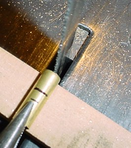
Next I cut a piece of 1/4" dia. brass tube and cut a slot in it for the sensor holder to fit into. You have to be careful here otherwise the blade will grab and damage it. You could do this by hand with a hacksaw. Then I ground the ends of it to a point like Craig's drawing. Then use some pliers to bend it to fit the holder.
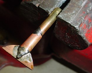
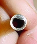
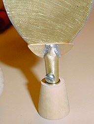
I inserted the 1/4" tube over a piece of 7/32" (which will fit exactly over my 3/16" drive shaft) and soldered it all together. You do have to be careful not to solder in between the holder halves where the sensor will slip between them.
then cut the remaining portion of the 7/32" off the bottom, grind it smooth on the emery belt and clean the whole thing up with the wire wheel and some finer emery paper. Don't worry too much about the solder job as will be using plumber's epoxy as filler/finsiher later before painting.
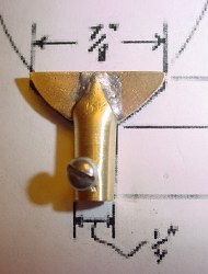
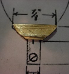
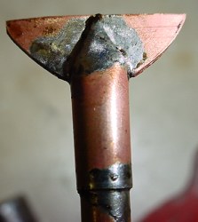
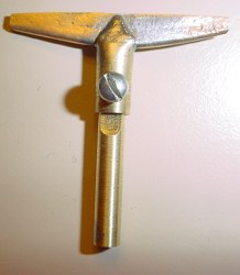
Here you can see how it matches up to the drawing. I drilled a #41 hole in the shaft and threaded it for a 4-40 round head machine screw. I didn't have a 4-40 tap, so I used a longer screw tapered the end on the emery belt and then held it with pliers and force screwed it through the hole with pressure to create the threads. You can get away with it on this relatively thin material. I used my wire strippers that have a 4-40 screw cutting hole to cut the screws as short as I could. All of this construction is to make it look like the original robot's sensor holders. Otherwise the screw is really sort of 'Rube-Golberg' or 'Erector Set' like.
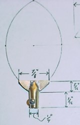
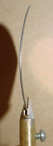
Here is another view of the holder, set screw and drive shaft. Note, the edges of the holder on the bottom will be filled with plumber's epoxy putty during finishing.

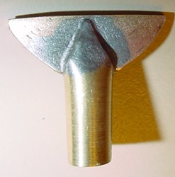
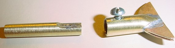
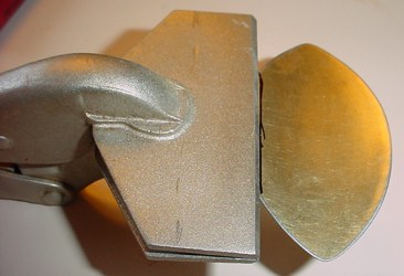
The left pic here shows the motor shaft end and the right pic is the sensor end
(see notes in the motorizing sensor page about making the "D" to fit the motor shaft).

You can see the back soldered up a little nicer than the front, but the finish out with some epoxy putty will cover little differences. It just depends on how picky you are.
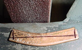
For the other holder I tried a little different approach. I started out with another longer piece of copper and bent it in half. I then flattened it over a piece of sensor material, again to allow for the sensor thickness to slip into it.
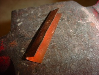
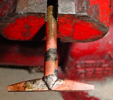
Then I took a scrap of sensor steel and cut the sensor radius on it. I slipped the copper over it and proceeded to try to shape it to the sensor radius by clamping it in the vise and hammering it to the shape. Not very high tech!
So then I marked it out using the scaled drawing as a guide and off to the emery sander again.
As you can see it is starting to take shape. Again keep some water nearby to cool the piece as you do this.
Same nested tubing sizes and soldering technique as above on the other sensor holder.
Cleaned up, screw installed, etc. same as the other sensor holder.
Sensors slipped into the slots.
Filled with plumber's epoxy putty and some sanding done prior to painting. Note I marked a line where the sensor fits centered in the holder, see next step.

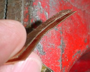
Rather than angle the sensor holder to hold this sensor vertical, I chose to make the holder straight and bend the bottom of the sensor so it stands straight in the holder.
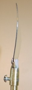

Now it is vertical.