Bob's Lost In Space B9 Robot Project | home
Misc. Parts | Motor Shaft Extensions | Knees & Hinges | Treadsections | Tread Making | TreadMaking from Tires | Drive Parts | Drive & Tread Installation | Tread movie | Barry's Tread Movies | Drive Upgrade | Legs | Donut & Waist plate | First Stackup | Torso | Neon | Arms | Microphone & Knob | Chest Buttons | Power Pack | Torso Vents Misc | Making Vents | Large Vent Drawings | Arm Mechanism #1 | B9 Arm Mech Dev. | Wrists & Claws | Collar | Radar | Motorizing Ears | Making Sensors | Brain | Brain Cup & Light Rods | Bulbs & Wiring Diagrams | My Old Robots | B9 Builder's & Info Sites | Related Links | Building Reference Info | Parts Drawing Links | Site Revisions | Final Leg Assembly | Leg & Hip Assembly | Leg-Hip Action | Non-B9 Projects | 2008 TX BUILD-OFF | 2008 TX BUILD-OFF PAGE 2 | RoboCon 2009
Treadsections
The Treadsections were made from Mark Thompson's Bermuda Triangle plans.
Since I'm motorizing these, I have added a few pieces for strength and distribution of the weight to the 1/2" panels. I used a good quality 1/2" & 3/16" birch plywood on the treadsections, it is very flat and has a fairly tight grain.
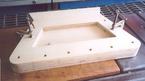
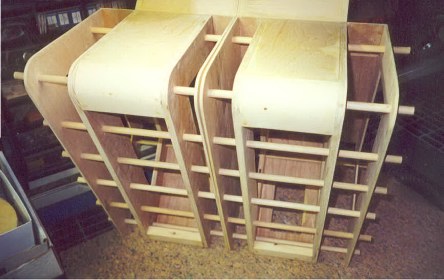
I first cut all the vertical pieces with my jigsaw. Then stacked them, clamped them and sanded all the edges smooth on my disc sander (just move the clamps around to sand all edges). This way they are all exactly the same. While they are still clamped I drilled the axle holes through all the pieces at once on the drill press.
After cutting the rest of the pieces I began to assemble them, using the dowels to keep everything perfectly in alignment. It is important to use very straight dowels and a perfectly flat surface to work on. To assemble, every joint is glued with wood glue and screwed together with drywall screws. All screw holes are pilot drilled and countersunk, to eliminate splitting. All edges, screw holes and defects are filled with wood filler and sanded, at least 2 times as wood filler shrinks.
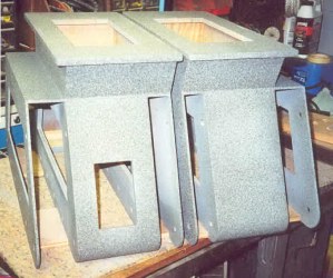
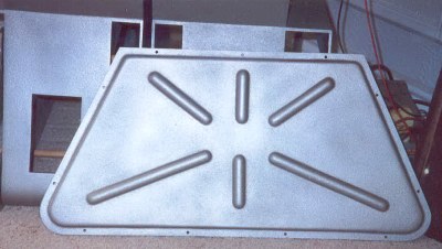
Another view from the top, you can see the piece with 4 screws is one I've added to the plans for additional strength.
You can see the three 3/4" pieces I've added to give a secure attachment of the top plate and to distribute the weight. Everything is glued then screwed. The 4 screws in a row attach a recessed 1/2" thick piece to provide support to the outer tread gable, you can just see it from underneath on the next photo on the right.
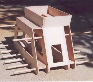
This is how you make everything line up. You can also see I've added the toe pieces. They're made from pine 2x4 scraps and shaped by sanding on a bench belt sander to fit perfectly. Again don't forget the wood glue. The glue adds tremendous strength to the joints and should prevent most future cracking of the seams through the finish. Use plenty and wipe off excess with a damp sponge.
Note one of the changes is that there is no bottom plate across both treadsections. The wooden axles will be replaced with steel axles when I install the wheels and bearings. The 1/2" diameter steel axles will prevent the need for the outer side gables to have to support much weight. Also, I will be using 8 axles continuous through both treadsections with a spacer between the 2 treadsections. The axles will be secured with cotter pins on the ends and locking collars between the treadsections.
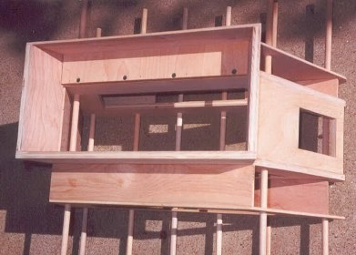
I will eventually make center bottom panels for each treadsection which will attach with screws or clips, removable for service.
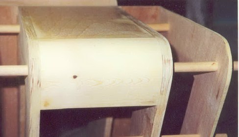
Here is a close-up of the toe installation. I used an orbital sander with 100 grit paper to final shape toe after installing.
Here is one of the slots in the knee plates for the hinges to fit into. I routed these with the Dremel tool and a simple wooden jig. The slots in the top kneeplates are offset by 1/2 the hinge thickness so the hinge stands vertical.
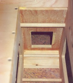
This is a shot of inside showing toe piece with groove in it for the axle to pass through.
After filling all holes and sanding, a sanding sealer is painted on. When dry it is lightly sanded again and then they can be primered. This is where you will see how good your filling was, any uneven seams or edges will show up through the primer. I used a sandable automotive gray primer. Get the orbital sander out again with some fresh paper clean up any areas that need it and refill if necessary, seal and prime. This is the method I used.
Pics after they were primed and first coat of texture before sanding it. I used plasti-kote - Fleck Stone - Faux Granite Base Coat. You can use any color though because the finish coat covers it. I will sand these lightly with 150 grit to take off the high spots and do another coat of primer before finish color coat. The primer coat will show me what the finish will look like to see if it is even enough. I think it should be like a slight orange peel effect.
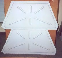
These are vacuum formed styrene sidepanels (from club member Norm Sockwell). The edges are left oversized so they can be trimmed to fit the treadsection.
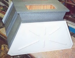
Here is a trimmed side panel with the holes drilled for mounting. About 1/2" all the way around is sufficient. It is best to check it against your treadsection, a little relief at the edge looks better to me, mabye in about 1/16" from the edge of your treadsection. Actually the lower left and right corners I trimmed the same 1/2" size as the rest of the flanges which does not follow the same contour as the actual treadsection toe profile. You may want to make the curves of your flanges match your treadsection's shape. I hate cutting styrene plastic and that's all I have to say about the cutting experience!
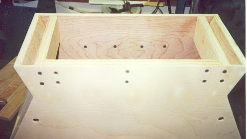
I used what seemed logical positions for mounting screws, although no screws were apparent on the original robot, this makes for easy mounting and removal. I drilled and pressed 6-32 Tee nuts into the wood treadsection sidepanels for the mounting screws to thread into. I did have to grind them down a little to match the thickness of my side gables. The picture didn't come out, pictures later.
I am using 6-32 flathead nickel plated machine screws cut to the length necessary not to interfere with the wheels inside. This method guarantees I'll never strip out screw threads.
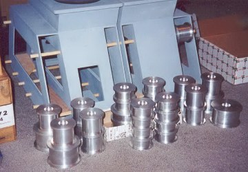
These are the aluminum wheels (from member Norm Sockwell). Each wheel gets 2 bearings. I'm making the 1/2" steel axles to mount them. I'm ordering .125" & .062" thick spacer bushings, 7/16 thick locking collars and hardware from McMaster-Carr that will be used to install axles & wheels.
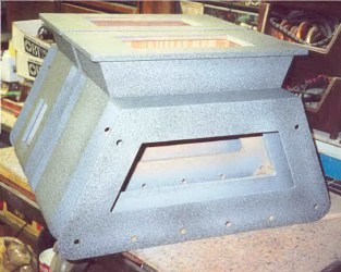
The textured treadsections have a coat of primer over the texture and are almost ready for the finish coats of paint. They're looking great.
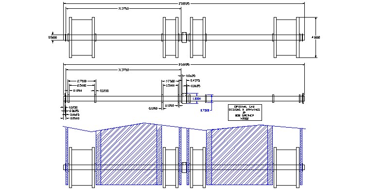
I know you can't see the detail here, but this is just to show the treadsection assembly. Click on drawing for larger version. Also note that my outer side gables are 3/16" thick instead of a full 1/4" which is more common, this affects the overall length of the axles so take that into account in your treadsection construction. The best way is to measure your final assembly for axle length, since construction methods and cut sizes may vary.
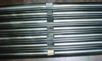
Here are 7 of my 8 steel 1/2" diameter axles showing the flats on the center of the shafts for the locking collars that go between the two treadsections. I first cut 4' lengths of 1/2" diameter steel rods into the 8 lengths and chucked them in the drill press and emery papered them until they fit through my bearings. The bearings were precision, the steel shaft was not. That was a money saving step, because precision diameter shaft is too expensive. These cost about $1.50 per foot.
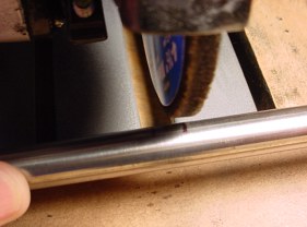
This pic shows how I used a grinding wheel to make them, marked it in ink and freehand ground the flats.
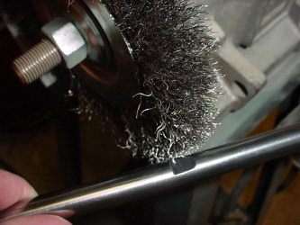
Cleaned them up and polished on the wire wheel.

The 7/16" thick x 1/2" I.D. x 1" O.D. locking collar that will be used and the flat for the set screw.
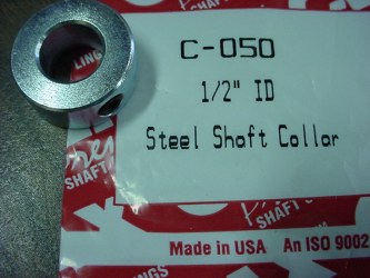
From our friends at McMaster Carr
(Much cheaper from them than if you buy them in a hardware store, if you can find them.)
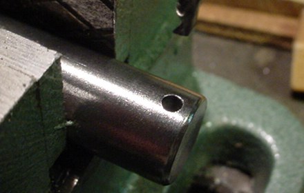
Each end of the axles gets a 1/8" hole drilled for the securing cotter pin. These holes should be accurately placed depending on the overall width of your treadsections, as is the length of your axles determined (see drawings above). If your axles are too long or the holes are in too far, you will not get the assembly together or your axle ends will interfere with the attachment of your sidepanels.

Again, you can clean and polish them with a wire wheel.
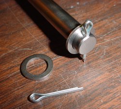
Cotter pin and bushing.
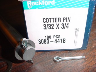
McMaster Carr again for the pins and bushings. Much cheaper than hardware store.
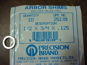
The bushings are called arbor shims, I used 2 thickness/sizes.
These are the .125 thickness.
I used 3/4" O.D. because they don't interfere with the outer race of the bearings in my wheels. A large washer would rub against the outer race of the bearings creating friction and wear. The inner race and the shim remain stationary with the axle.
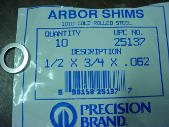
These are the .062 thickness.
Review my drawings for locations of the two thicknesses.
Again all this may vary due to your particular construction techniques.
Go to Treadmaking